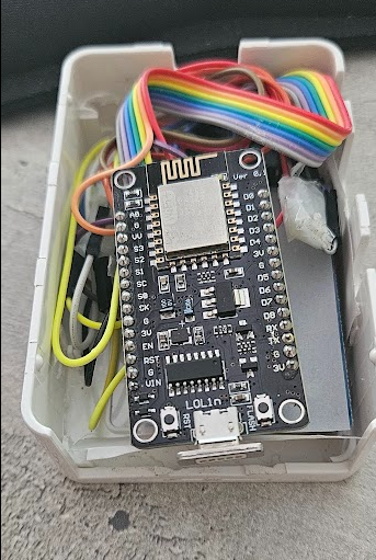
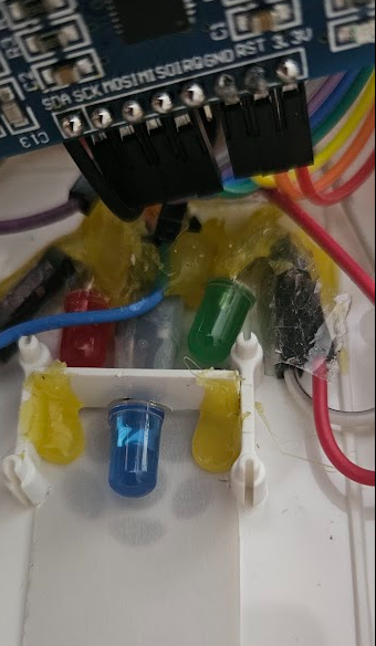
Hi everyone, here’s a little tutorial to create a badge reader that I inserted into a Raspberry case. The LED changes from green to red depending on the alarm status. Green for disarmed, red for armed. Blue LED in the center to confirm badge reading.
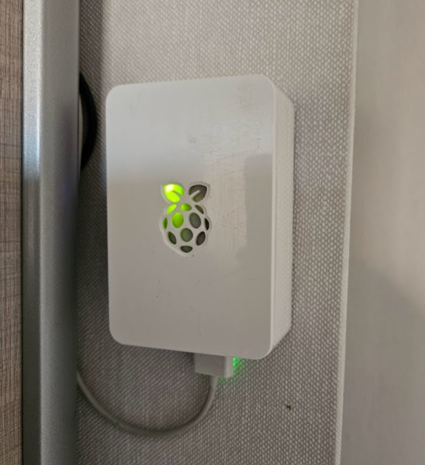
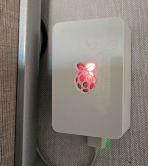
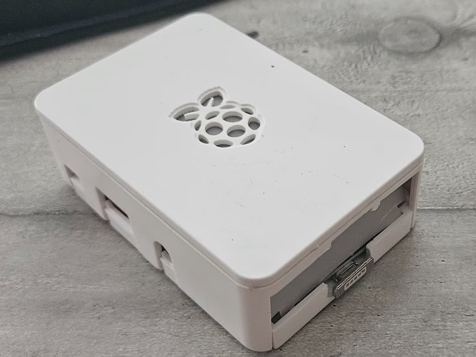
Since each badge is read and transmitted to Gladys, you can thus create all the scenes you want depending on each person who badges.
Operation:
When the module is powered on, it sends the code 000 on the topic(1) mentioned in the code and reads the value of the alarm topic(2) in order to display the corresponding LED color (alarm active or not).
If you change the buzzer value to D3, on startup it will beep 3 times: 2 short and 1 long
When you pass a badge, the blue light turns on and the buzzer sounds once to confirm its reading. The badge code is sent on the topic(1). The scene you have created takes over…
Prerequisites
You will need:
-
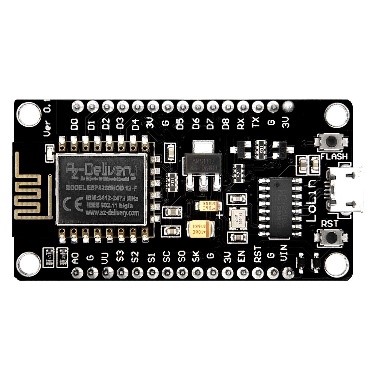
An ESP8266 (or another one but with wifi to connect to the network) I took a CH340, maybe a bit too bulky! https://fr.aliexpress.com/item/1005005977505151.html?spm=a2g0o.productlist.main.7.647f7f5ctaqyqh&algo_pvid=becabac8-c2cb-49cc-8574-7415dabb1045&aem_p4p_detail=202311020929461581501114134080000486307&algo_exp_id=becabac8-c2cb-49cc-8574-7415dabb1045-3&pdp_npi=4%40dis!EUR!7.52!0.49!!!56.98!!%40211b600416989425860946543e7998!12000035141219305!sea!FR!0!AB&curPageLogUid=z6UFtqB4HZ6K&search_p4p_id=202311020929461581501114134080000486307_4
-
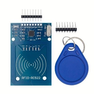
An RFID reader of this type with at least one badge. https://fr.aliexpress.com/item/4000029144197.html?spm=a2g0o.productlist.0.0.63901cfaJ5YwjT&algo_pvid=null&algo_expid=null&btsid=0b0a556f16215414175431574e32da&ws_ab_test=searchweb0_0%2Csearchweb201602_%2Csearchweb201603_&gatewayAdapt=glo2fra
-
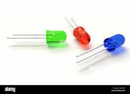
3V LEDs if you want a visual feedback of the alarm status.
-
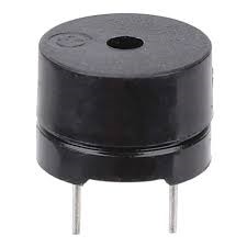
A buzzer to ensure badge reading
-
Some connecting wires.
-
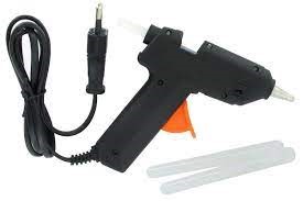
A glue gun or other fixing system
-
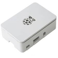
A case to house everything.
-
A bit of tracing paper if the case is drilled like mine (raspberry)
-
Small fingers to fit everything without forcing.
Software Side:
Arduino. You can download it here:
https://www.arduino.cc/en/software
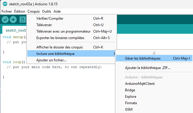
Add the following libraries:
- ESP8266WiFi.h
- ESP8266WiFiMulti.h
- PubSubClient.h
- SPI.h
- MFRC522.h
- NTPClient.h
- WiFiUdp.h
Connect your ESP8266 and check that it is well recognized.
The driver for ESP8266 copies on aliexpress can be found here:
Follow the installation tutorial.
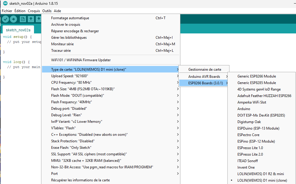
In Arduino, choose the COM port that corresponds to your little beast:
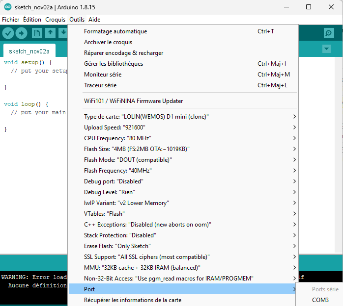
Choose your board (For ESP8266 board copies, I use this board ref:
Programming
In order for the reader to be able to communicate the read code to Gladys, you need to create 2 MQTT fake-devices.
In the MQTT integration, create 2 « fake device » like this:
- Reading the alarm code that you will need to set to a value of 0 to 1000000000000. This allows for a wide (very wide) opening to the codes received. I used the « access control » type.
→ Indicated Link1 in the code
- An alarm switch that activates to 0 or 1 depending on the alarm status. I used the « Power » type.
→ Indicated Link2 in the code
Integration:

Fake devices:
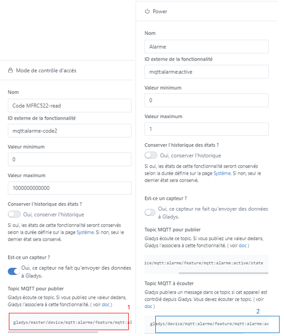
Make sure to get the Topic addresses that you will need to indicate in the code for the ESP8266.
Code:
It probably contains some gross errors that will make some eyes bleed but I managed to make it run with my limited coding skills, which is a great feat!  It is therefore very perfectible ..
I added a restart every 24 hours because, for some reason, the code runs out after a while and the module no longer picks up the badges. If one of you understands the problem ..
#include <ESP8266WiFi.h>
#include <ESP8266WiFiMulti.h>
#ininclude <PubSubClient.h>
#include <SPI.h>
#include <MFRC522.h>
#include <NTPClient.h>
#include <WiFiUdp.h>

int Buzzer = D4; //for ESP8266 Microcontroller
#define SS_PIN D8
#define RST_PIN D0

#define alarme_code " Lien1"  //Topic Gladys alarme code

MFRC522 rfid(SS_PIN, RST_PIN); // Instance of the class

MFRC522::MIFARE_Key key;

WiFiUDP ntpUDP;
NTPClient timeClient(ntpUDP, "europe.pool.ntp.org", 3600, 60000);

long lastMsg = 0;   //Timestamp of the last message published on MQTT
long lastRecu = 0;

// Init array that will store new NUID
byte nuidPICC[4];

//WIFI
const char* ssid = "your network SSID name";
const char* password = "your wifi code";
const char* code = "";

//MQTT
#define MQTT_BROKER       "broker IP address"
#define MQTT_BROKER_PORT  1883
#define MQTT_USERNAME     "MQTT broker username"
#define MQTT_KEY          "broker password"


ESP8266WiFiMulti WiFiMulti;
WiFiClient espClient;
PubSubClient client(espClient);


void setup() {
  Serial.begin(115200);
  setup_wifi();
  setup_mqtt();
  setup_RFID();

  pinMode (Buzzer, OUTPUT);
client.setCallback(callback);

pinMode(D1, OUTPUT);
pinMode(D2, OUTPUT);
pinMode(D3, OUTPUT);
     digitalWrite(D1,LOW);
     digitalWrite(D2,LOW);
     digitalWrite(D3,LOW);
          delay(200);
     digitalWrite (Buzzer, HIGH); //turn buzzer on
          delay(200);
      digitalWrite (Buzzer, LOW);  //turn buzzer off
         delay(200);
     digitalWrite (Buzzer, HIGH); //turn buzzer on
          delay(200);
      digitalWrite (Buzzer, LOW);  //turn buzzer off
          delay(500);
    digitalWrite (Buzzer, HIGH); //turn buzzer on
          delay(500);
     digitalWrite (Buzzer, LOW);  //turn buzzer off

  // Subscribe to the MQTT topic for alarm activation by button
  client.subscribe("Lien2 ");

 client.publish(alarme_code, "000", true);   //Publish a code on the alarme_code topic

   }

void restartESP() {
  ESP.restart(); // Software restart of the ESP8266
}

void setup_wifi(){
  //connect to wifi
  WiFiMulti.addAP(ssid, password);
  while ( WiFiMulti.run() != WL_CONNECTED ) {
    delay ( 500 );
    Serial.print ( "." );
  }
  Serial.println("");
  Serial.println("WiFi connected");
  Serial.print("MAC : ");
  Serial.println(WiFi.macAddress());
  Serial.print("IP Address : ");
  Serial.println(WiFi.localIP());

}
void setup_mqtt(){
  client.setServer(MQTT_BROKER, MQTT_BROKER_PORT);
  client.setCallback(callback);//Declare the subscription function
  reconnect();
}

/**
 *    Helper routine to dump a byte array as hex values to Serial.
*/
void printHex(byte *buffer, byte bufferSize) {
  for (byte i = 0; i < bufferSize; i++) {
    Serial.print(buffer[i] < 0x10 ? " 0" : " ");
    Serial.print(buffer[i], HEX);
  }
}

void setup_RFID(){
  SPI.begin(); // Init SPI bus
  rfid.PCD_Init(); // Init MFRC522
  Serial.println();
  Serial.print(F("Reader :"));
  rfid.PCD_DumpVersionToSerial();

  for (byte i = 0; i < 6; i++) {
    key.keyByte[i] = 0xFF;
  }
  Serial.println();
  Serial.println(F("This code scan the MIFARE Classic NUID."));
  Serial.print(F("Using the following key:"));
  printHex(key.keyByte, MFRC522::MF_KEY_SIZE);
}

void callback(char* topic, byte* payload, unsigned int length) {
  String value = "";
  for (int i = 0; i < length; i++) {
    value += (char)payload[i];
  }
  Serial.print("Current value = ");
  Serial.println(value);

  Serial.println("-------New message from the mqtt broker-----");
   Serial.print("Channel:");
   Serial.println(topic);
   Serial.print("data:");
   Serial.write(payload, length);
   Serial.println();
   if ((char)payload[0] == '1') { //To be set for LED on or off
     Serial.println("LED ON");
      digitalWrite(D2,LOW);
      digitalWrite(D1,HIGH);
      digitalWrite (Buzzer, HIGH); //turn buzzer on
      delay(1000);
     digitalWrite (Buzzer, LOW); //turn buzzer off
      Serial.println("alarm on");

   } else if ((char)payload[0] == '0'){
     Serial.println("LED OFF");
     digitalWrite(D1,LOW);
      digitalWrite(D2,HIGH);
      digitalWrite (Buzzer, HIGH); //turn buzzer on
     delay(1000);
     digitalWrite (Buzzer, LOW); //turn buzzer off
     Serial.println("alarm off");

   }
 }


void reconnect(){
  while (!client.connected()) {
    Serial.println("Connecting to MQTT server ...");
    if (client.connect("ESPClient", MQTT_USERNAME, MQTT_KEY)) {
      Serial.println("MQTT connected");
          }
    else {
      Serial.print("failed, error code= ");
      Serial.println(client.state());
      Serial.println("new attempt in 2s");
    delay(2000);
    }
  }
  client.subscribe("Lien2");// Subscribe to the MQTT topic for alarm status
}

/**
   Helper routine to dump a byte array as dec values to Serial.
*/
void printDec(byte *buffer, byte bufferSize) {
  String payload = "";
  String topic = " Lien1";
  for (byte i = 0; i < bufferSize; i++) {
    Serial.print(buffer[i] < 0x10 ? " 0" : "");
    Serial.print(buffer[i], DEC);
    payload += String(buffer[i]); // Added by ChatGPT script
      if (i != bufferSize - 1) { // Added by ChatGPT script
        payload += ""; // Added by ChatGPT script
      }
  }
client.publish(topic.c_str(), payload.c_str());
}


void loop() {
    if (millis() >= 86400000) { // Check if 24 hours have passed (86,400,000 milliseconds)
  Serial.print ("24 hours passed");
    ESP.restart(); // Call the function to restart the ESP8266
  }
  reconnect();
  client.loop();
  float temp = 0;
  // Reset the loop if no new card present on the sensor/reader. This saves the entire process when idle.
  if ( ! rfid.PICC_IsNewCardPresent())
    return;

  // Verify if the NUID has been readed
  if ( ! rfid.PICC_ReadCardSerial())
    return;

  Serial.print(F("PICC type: "));
  MFRC522::PICC_Type piccType = rfid.PICC_GetType(rfid.uid.sak);
  Serial.println(rfid.PICC_GetTypeName(piccType));

  // Check is the PICC of Classic MIFARE type
  if (piccType != MFRC522::PICC_TYPE_MIFARE_MINI &&
      piccType != MFRC522::PICC_TYPE_MIFARE_1K &&
      piccType != MFRC522::PICC_TYPE_MIFARE_4K) {
    Serial.println(F("Your tag is not of type MIFARE Classic."));
    return;
  }
    Serial.println(F("A new card has been detected."));
    // Store NUID into nuidPICC array
    for (byte i = 0; i < 4; i++) {
      nuidPICC[i] = rfid.uid.uidByte[i];
    }
    Serial.println(F("The NUID tag is:"));
    Serial.print(F("In hex: "));
    printHex(rfid.uid.uidByte, rfid.uid.size);
    Serial.println();
    Serial.print(F("In dec: "));
    printDec(rfid.uid.uidByte, rfid.uid.size);
    Serial.println();

      digitalWrite(D3,HIGH); // Blue LED on
      digitalWrite (Buzzer, HIGH); //turn buzzer on
      delay(1000);
      digitalWrite (Buzzer, LOW); //turn buzzer off
      digitalWrite(D3,LOW); // Blue LED off

 long now = millis();
 if (now - lastMsg > 1000 * 60) {
    lastMsg = now;

 }
  // Halt PICC
  rfid.PICC_HaltA();

  // Stop encryption on PCD
  rfid.PCD_StopCrypto1();
}
Remember to modify these values according to your own installation :
• const char* ssid = « your network SSID name »;
• const char* password = « your wifi code »;
• #define MQTT_BROKER « broker IP address »
• #define MQTT_BROKER_PORT 1883
• #define MQTT_USERNAME « MQTT broker username »
• #define MQTT_KEY « broker password »
The connection :
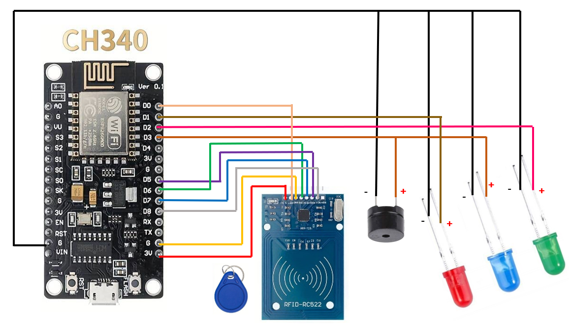
The buzzer is connected with the blue LED to be informed visually and audibly.
If you want a blue LED/buzzer blinking at module startup, change the value D4 to D3 here :
int Buzzer = D4
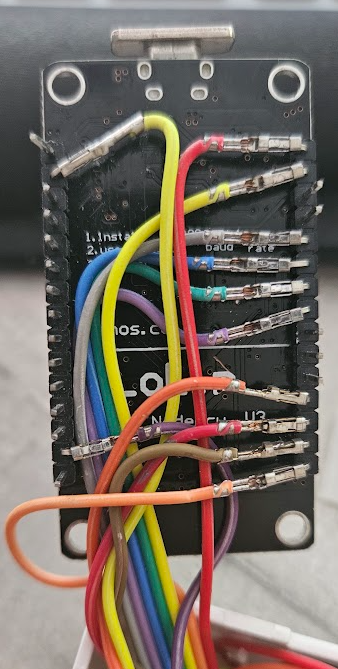
You display the « access control » boxes on your dashboard, you power your badge reader and you swipe a badge. Normally you will hear the beep, see the blue light and receive the read code on the dashboard. For security, displaying the code is not to be left on the dashboard, it only serves to retrieve the values in setup mode. Gladys Scenes: Finally, to work with the new Gladys alarm system, you need to create 2 reversed scenes. Badge alarm activation: - When the read code (fake device access control 1) is = to (your badge value) then, - If the house is disarmed • House arming • « Control a device » (fake device power 2) and set it to 1 Badge alarm deactivation: - When the read code (fake device access control 1) is = to (your badge value) then, - If the house is armed • House disarming • « Control a device » (fake device power 2) and set it to 0 In the trigger, you can add multiple code boxes to check. You can add a delay in your badge activation scene between the badge reading and the house arming to give yourself time to leave. Personally, I added Google Home messages that warn to leave the house when the badge is activated, 3 minutes later then 4 then at arming. I hope I am clear enough and that it will suit your use. Your turn and good luck ..


