Salut tout le monde, petit tutoriel pour créer émetteur de commande somfy.
Fonctionnement :
Ce tuto vous permet de réaliser un émetteur 433.42mhz connecté en wifi au broker mqtt de Gladys et des boutons de commandes type volet.
Vous pourrez ainsi commander des stores, volets roulants ou autre système fonctionnant sur le principe de commande Somfy.
Prérequis
Vous aurez besoin de :
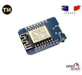
- Un ESP8266 mini board (ou autre mais avec wifi pour se connecter au réseau et 5v sur broches)
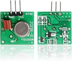
- Un émetteur 433mhz avec résonateur circulaire.
- Un résonateur de filtre SAW, cristal de quartz, 433.42MHz, le .42mhz est très important. En effet, le résonateur des émetteurs ne convient pas.
- 1 antenne ressort
- 1 LED 5v pour confirmer l’émission du signal.
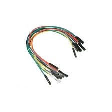
- Quelques fils de raccordements.
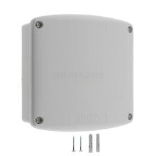
- Un boitier pour loger tout ça. Vous avez le choix mais pas trop épais pour ne pas bloquer le signal.


- un fer à souder avec de l’étain
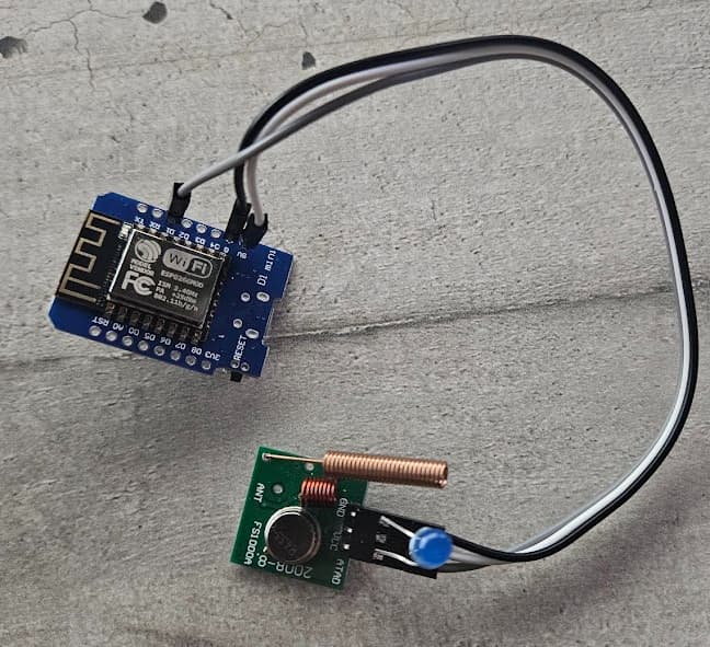
Raccordement
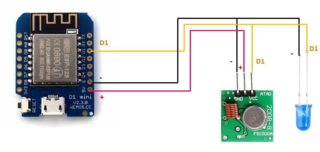
L’étape la plus délicate est de retirer le résonateur sur l’émetteur pour souder son remplaçant.
La LED bleue scintillera à chaque envoi de code entre l’ESP8266 et l’émetteur. Petite vérif pour s’assurer que tout fonctionne bien !
Coté Logiciel :
- Arduino. Vous pouvez le télécharger ici :
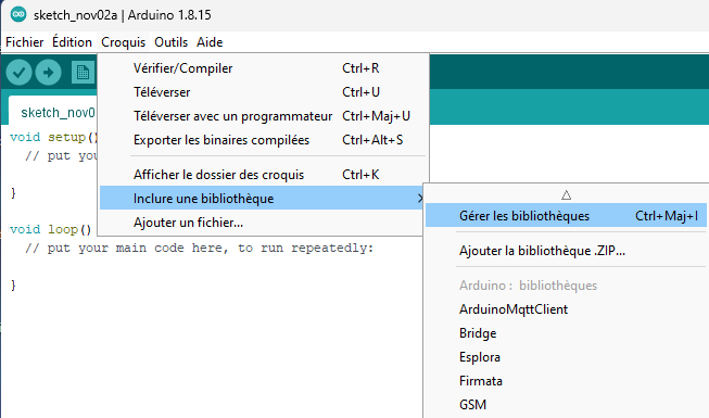
- Ajouter des bibliothèques suivantes :
- ESP8266WiFi.h
- EEPROM.h
- PubSubClient.h
- AsyncElegantOTA.h
Connectez votre ESP8266 et vérifier qu’il soit bien reconnu.
Le driver des copies d’ESP8266 sur aliexpress peut être trouvé ici :
Suivez le tuto d’installation.
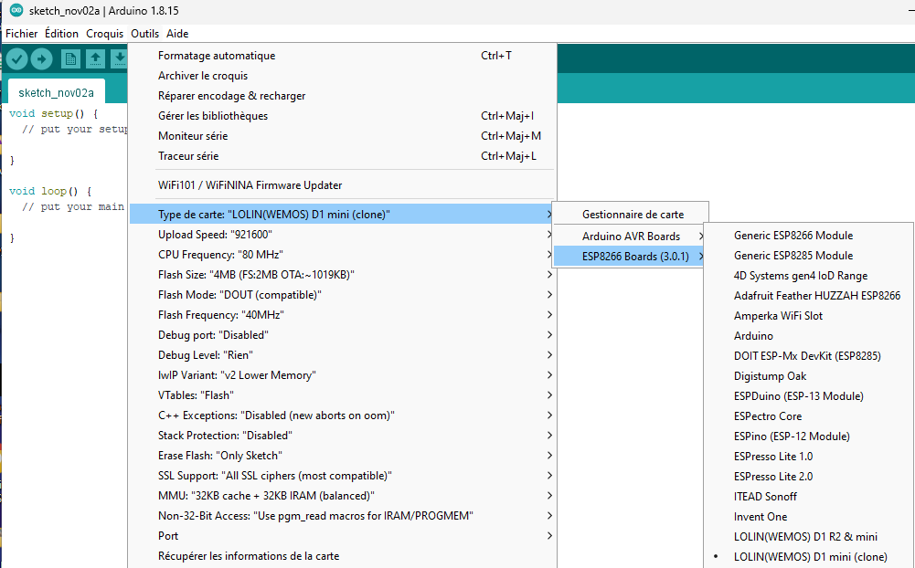
Dans Arduino, choisissez le port COM qui correspond à votre petite bête :
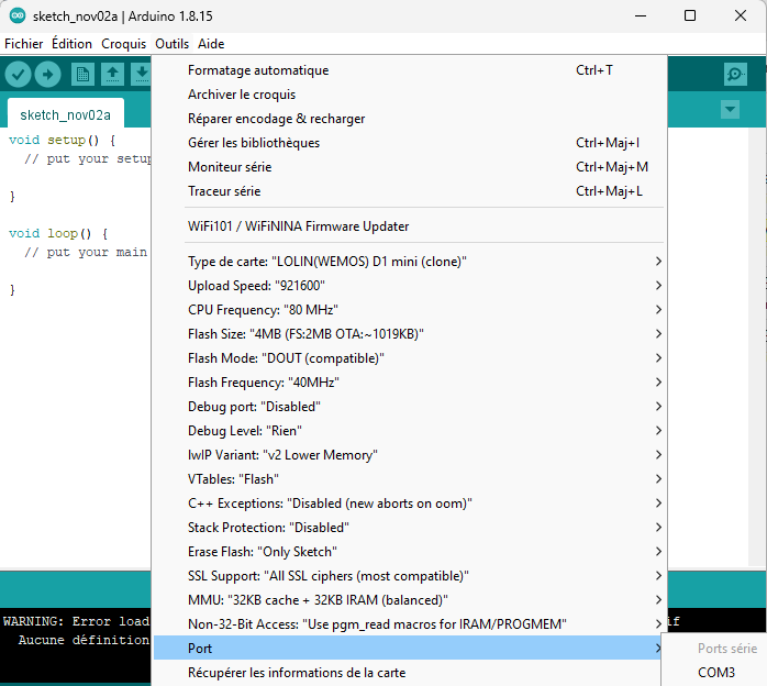
Choisissez votre carte (Pour des copies de cartes ESP8266, j’utilise cette ref de carte :
![]()
Programmation
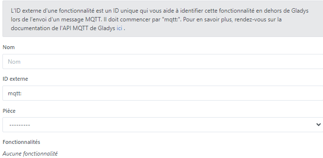
Afin que les boutons Gladys puissent envoyer les valeurs attendues par l’émetteur, il vous faut créer plusieurs fakes-device MQTT.
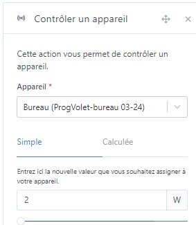
Dans l’intégration MQTT, créez 2 « fake device » :
- Commande du volet avec ses 3 boutons qui enverront les valeurs -1, 0 et 1.
- Un commutateur variateur qui s’active de 2 à 6 inclus pour programmer et créer l’interface de code entre le bouton volet et votre module.
Indiqué Lien1 dans le code
Vous pouvez créer un autre fake device texte afin de voir dans Gladys le retour de commande pris en compte par l’émetteur. C’est prévu dans le code, sinon ne mettez rien.
Indiqué Lien2 dans le code

![]()
![]()
![]()
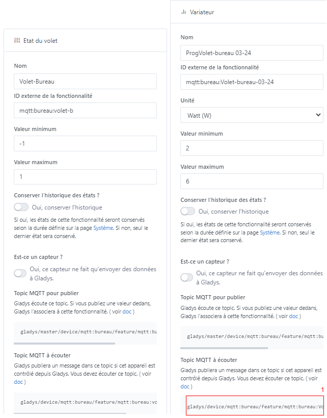

Récupérer bien les adresses de Topic qu’il vous faudra indiquer dans le code pour l’ESP8266.
Code :
Il contient sans doute des grossières erreurs mais j’ai réussi à le faire tourner avec mes faibles compétences en codage. Il est donc très perfectible … ![]()
Je ne suis pas le créateur du code, je n’en tire donc pas les mérites. J’ai juste adapté pour qu’il accepte des valeurs chiffres au lieu de lettres.
2 = Down
3 = Stop
4 = Up
5 = Prog
6 =
Le 6 est volontairement laissé vide afin de réaliser la programmation avec la commande d’origine.
Si vous souhaitez créer de multiples télécommandes ou si vous devez réenregistrer après modification, pensez à incrémenter cette valeur comme indiqué dans l‘exemple pour chacun des émetteurs : #define REMOTE 0x122000
/* This sketch allows you to emulate a Somfy RTS or Simu HZ remote.

   This is a fork of the original sketch written by Nickduino (https://github.com/Nickduino)

   If you want to learn more about the Somfy RTS protocol, check out https://pushstack.wordpress.com/somfy-rts-protocol/

   The rolling code will be stored in EEPROM, so that you can power the D1 Mini.

   Easiest way to make it work for you:
    - Choose a remote number
    - Choose a starting point for the rolling code. Any unsigned int works, 1 is a good start
    - Upload the sketch
    - Long-press the program button of YOUR ACTUAL REMOTE until your blind goes up and down slightly
    - send 'p' to the serial terminal oder via 'MQTT'
   To make a group command, just repeat the last two steps with another blind (one by one)

   Then:
    - u will make it to go up
    - s make it stop
    - d will make it to go down
    - p sets the program mode
    - you can also send a HEX number directly for any weird command you (0x9 for the sun and wind detector for instance)
*/

#include <EEPROM.h>
#include <ESP8266WiFi.h>
#include <PubSubClient.h>
#include <AsyncElegantOTA.h>

WiFiClient espClient;
PubSubClient client(espClient);

String header;
const char* ssid = "xx";   // <-- Enter your Wifi-SSID
const char* password = "xx";  // <-- Enter your Wifi-Password

const char* mqtt_server = "xx";  // <-- Enter the IP of your MQTT-Server
const unsigned int mqtt_port = 1883;
const char* mqtt_user =   "xx";
const char* mqtt_password =   "xx"; // <-- Enter the Password of your MQTT-Server
String clientId = "Awning";

// Paramètres du topic MQTT
const char* topic = "lien1"; // <-- Le topic variateur avec code chiffre
const char* topic2 = "lien2"; // <-- Le topic texte retour de commande

#define SYMBOL 640
#define UP 0x2
#define STOP 0x1
#define DOWN 0x4
#define PROG 0x8
#define EEPROM_ADDRESS 0
#define REMOTE 0x121000    //<-- Change it to a unique no., if you have more than one Remote (0x121305, 0x121306, 0x121307, ...)

AsyncWebServer server(80);

char demand = '6'; // w = waiting

const int transmitPin = D1;

unsigned long rollingCode = 1;

byte frame[7];
byte checksum;


void BuildFrame(byte *frame, byte button) {
  unsigned int code;
  EEPROM.get(EEPROM_ADDRESS, code);
  frame[0] = 0xA7; // Encryption key. Doesn't matter much
  frame[1] = button << 4;  // Which button did  you press? The 4 LSB will be the checksum
  frame[2] = code >> 8;    // Rolling code (big endian)
  frame[3] = code;         // Rolling code
  frame[4] = REMOTE >> 16; // Remote address
  frame[5] = REMOTE >>  8; // Remote address
  frame[6] = REMOTE;       // Remote address

  Serial.print("Frame         : ");
  for(byte i = 0; i < 7; i++) {
    if(frame[i] >> 4 == 0) { //  Displays leading zero in case the most significant
      Serial.print("0");     // nibble is a 0.
    }
    Serial.print(frame[i],HEX); Serial.print(" ");
  }

// Checksum calculation: a XOR of all the nibbles
  checksum = 0;
  for(byte i = 0; i < 7; i++) {
    checksum = checksum ^ frame[i] ^ (frame[i] >> 4);
  }
  checksum &= 0b1111; // We keep the last 4 bits only


//Checksum integration
  frame[1] |= checksum; //  If a XOR of all the nibbles is equal to 0, the blinds will
                        // consider the checksum ok.

  Serial.println(""); Serial.print("With checksum : ");
  for(byte i = 0; i < 7; i++) {
    if(frame[i] >> 4 == 0) {
      Serial.print("0");
    }
    Serial.print(frame[i],HEX); Serial.print(" ");
  }


// Obfuscation: a XOR of all the bytes
  for(byte i = 1; i < 7; i++) {
    frame[i] ^= frame[i-1];
  }

  Serial.println(""); Serial.print("Obfuscated    : ");
  for(byte i = 0; i < 7; i++) {
    if(frame[i] >> 4 == 0) {
      Serial.print("0");
    }
    Serial.print(frame[i],HEX); Serial.print(" ");
  }
  Serial.println("");
  Serial.print("Rolling Code  : "); Serial.println(code);
  EEPROM.put(EEPROM_ADDRESS, code + 1); //  We store the value of the rolling code in the
                                        // EEPROM. It should take up to 2 adresses but the
                                        // Arduino function takes care of it.
 EEPROM.commit();
}


void SendCommand(byte *frame, byte sync) {
  if(sync == 2) { // Only with the first frame.
  //Wake-up pulse & Silence
    digitalWrite(transmitPin, HIGH);
    delayMicroseconds(9415);
    digitalWrite(transmitPin, LOW);
    delayMicroseconds(89565);
  }

// Hardware sync: two sync for the first frame, seven for the following ones.
  for (int i = 0; i < sync; i++) {
    digitalWrite(transmitPin, HIGH);
    delayMicroseconds(4*SYMBOL);
    digitalWrite(transmitPin, LOW);
    delayMicroseconds(4*SYMBOL);
  }

// Software sync
  digitalWrite(transmitPin, HIGH);
  delayMicroseconds(4550);
  digitalWrite(transmitPin, LOW);
  delayMicroseconds(SYMBOL);


//Data: bits are sent one by one, starting with the MSB.
  for(byte i = 0; i < 56; i++) {
    if(((frame[i/8] >> (7 - (i%8))) & 1) == 1) {
      digitalWrite(transmitPin, LOW);
      delayMicroseconds(SYMBOL);
      digitalWrite(transmitPin, HIGH);
      delayMicroseconds(SYMBOL);
    }
    else {
      digitalWrite(transmitPin, HIGH);
      delayMicroseconds(SYMBOL);
      digitalWrite(transmitPin, LOW);
      delayMicroseconds(SYMBOL);
    }
  }

  digitalWrite(transmitPin, LOW);
  delayMicroseconds(30415); // Inter-frame silence
}


void callback(char* topic, byte* payload, unsigned int length) {
    if (strcmp(topic,"lien1") == 0) {
      char demand_str[length + 1];
      strncpy (demand_str, (char*)payload, length);
      demand_str[length] = '\0';
      Serial.println(demand_str);

      // u = up, d = down, s = stop, p = program, w = wait

      if (strcmp(demand_str,"4") == 0) {
        demand = '4';
      } else if (strcmp(demand_str,"2") == 0) {
        demand = '2';
      } else if (strcmp(demand_str,"3") == 0) {
        demand = '3';
      } else if (strcmp(demand_str,"5") == 0) {
        demand = '5';
      } else {
        demand = '6';
      }
      Serial.println(demand_str);
      Serial.println(demand);
    }
}

void setup() {
  Serial.begin(115200);
  Serial.println(" ");
  Serial.println("Starting Somfy");
  Serial.println();
  Serial.print("Connecting to ");
  Serial.println(ssid);
  WiFi.mode(WIFI_STA);
  WiFi.begin(ssid, password);
  WiFi.hostname("Box-Somfy");

  while (WiFi.status() != WL_CONNECTED) {
    delay(500);
    Serial.print(".");
  }
  Serial.println("");
  Serial.println("WiFi connected");

  Serial.println(WiFi.localIP());

  pinMode(transmitPin, OUTPUT); // Pin D1 on the Wemos D1 mini
  digitalWrite(transmitPin, LOW);

  client.setServer(mqtt_server, mqtt_port);
  client.setCallback(callback);

  server.on("/", HTTP_GET, [](AsyncWebServerRequest *request) {
  request->send(200, "text/plain", "Hi! I am a Wemos D1 mini.");
  });

  AsyncElegantOTA.begin(&server);    // Start ElegantOTA
  server.begin();


  EEPROM.begin(4);
  EEPROM.get(EEPROM_ADDRESS, rollingCode);

  Serial.println(" ");
  Serial.print("Simulated remote number : ");
  Serial.println(REMOTE, HEX);
  Serial.print("Current rolling code    : ");
  Serial.println(rollingCode);
}

void reconnect() {
  // Boucle de reconnexion au broker MQTT
  while (!client.connected()) {
    Serial.println("Attempting MQTT connection...");
    if (client.connect("WemosClient", mqtt_user, mqtt_password)) {
      Serial.println("Connected to MQTT");
      // Abonnement au topic MQTT
      client.subscribe(topic);
    } else {
      Serial.print("Failed, rc=");
      Serial.print(client.state());
      Serial.println(" Retrying in 5 seconds...");
      delay(5000);
    }
  }
}

void loop() {
  AsyncElegantOTA.loop();

// Vérification de la connexion au broker MQTT
  if (!client.connected()) {
    reconnect();
  }
  // Mise à jour du client MQTT
  client.loop();

  if (demand == '4' || demand == '2' || demand == '3' || demand == '5') {

//    char serie = (char)Serial.read();
    char serie = (char)demand;
    if(serie == '4') {
      demand = '4';
      Serial.println("up"); // Somfy is a French company, after all.
      BuildFrame(frame, UP);

      client.publish(topic2, "up");
      delay(50);
      client.subscribe(topic2);
      Serial.println("moving up");
    }
    else if(serie == '2') {
      demand = '2';
      Serial.println("down");
      BuildFrame(frame, DOWN);
      client.publish(topic2, "down");
      delay(50);
      client.subscribe(topic2);
      Serial.println("moving down");
    }
    else if(serie == '5') {
      demand = '5';
      Serial.println("prog");
      BuildFrame(frame, PROG);
      client.publish(topic2, "prog");
      delay(50);
      client.subscribe(topic2);
      Serial.println("prog mode");
    }
    else if(serie == '3') {
      demand = '3';
      Serial.println("stop");
      BuildFrame(frame, STOP);
      client.publish(topic2, "stop");
      delay(50);
      client.subscribe(topic2);
      Serial.println("stop");
    }

    demand = '6';

    Serial.println("");
    SendCommand(frame, 2);
    for(int i = 0; i<2; i++) {
      SendCommand(frame, 7);
    }
  }
}
Pensez à modifier ces valeurs suivant votre propre installation :
• const char* ssid = « votre nom de réseau SSID »;
• const char* password = « vode code wifi »;
• #define MQTT_BROKER « adresse IP du broker »
• #define MQTT_BROKER_PORT 1883
• #define MQTT_USERNAME « non d’utilisateur broker MSTT »
• #define MQTT_KEY « mot de passe du broker »
Si vous utilisez ce code pour plusieurs modules sur le même broker mqtt, pensez à modifier cette valeur dans la partie « void reconnect » :
if (client.connect(« WemosClient2 », mqtt_user, mqtt_password)) {
Scènes Gladys :
Enfin pour fonctionner avec le nouveau système d’alarme de Gladys, il vous faut créer 3 scènes de commandes volet sur la base de celle-ci :
Baisser volet : -1 → 2
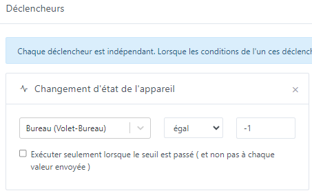
Idem pour Stop : 0 → 3
Idem pour Monter : 1 → 4
Enregistrement du nouveau module sur le volet.
Dernière étape, passer le volet en mode enregistrement de nouvelle télécommande. Vous devriez avoir sur votre télécommande un bouton programmation qu’il faut presser quelques secondes. Le volet devrait monter et descendre un peu pour confirmer.
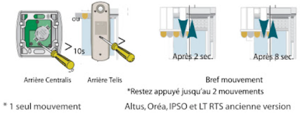
Dans Gladys, passez le variateur sur 5. Le volet devrait réagir et répéter le mouvement.
Si oui, c’est terminé ![]()
Sinon retentez en basculant le variateur sur 6 puis 5. Il peut arriver qu’il faille changer le code pour que le volet interprète ça comme une nouvelle télécommande.
Le volet sort tout seul du mode enregistrement télécommande.
Bon courage.
Tiboys