Hello everyone, a small tutorial to create a Somfy command emitter.
Operation:
This tutorial allows you to create a 433.42MHz emitter connected via WiFi to the Gladys MQTT broker and command buttons for roller shutters.
You will thus be able to control blinds, roller shutters or any other system working on the principle of Somfy command.
Prerequisites
You will need:
- An ESP8266 mini board (or another one but with WiFi to connect to the network and 5V on pins)
- A 433MHz transmitter with a circular resonator.
- A SAW filter resonator, quartz crystal, 433.42MHz, the .42MHz is very important. Indeed, the resonator of the transmitters does not work.
- 1 spring antenna
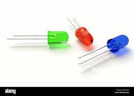
- 1 5V LED to confirm the signal emission.
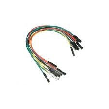
- Some connecting wires.
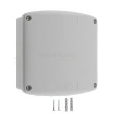
- A case to house all this. You have the choice but not too thick to not block the signal.
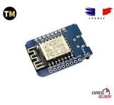
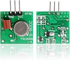
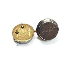
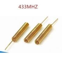
- a soldering iron with solder
Connection
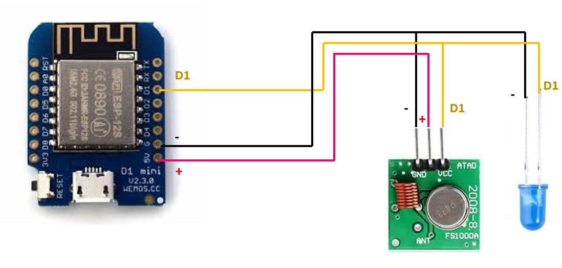
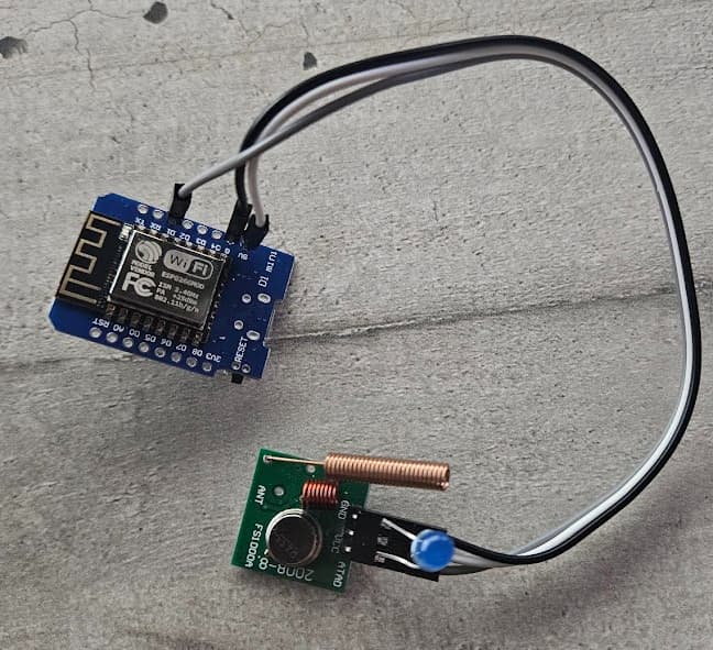
The most delicate step is to remove the resonator on the transmitter to solder its replacement.
The blue LED will flash with each code sent between the ESP8266 and the transmitter. A small check to make sure everything works well!
Software Side:
- Arduino. You can download it here:
- Add the following libraries:
- ESP8266WiFi.h
- EEPROM.h
- PubSubClient.h
- AsyncElegantOTA.h
Connect your ESP8266 and check that it is well recognized.
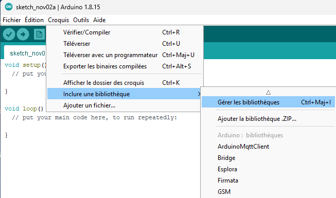
The driver for ESP8266 copies on aliexpress can be found here:
Follow the installation tutorial.
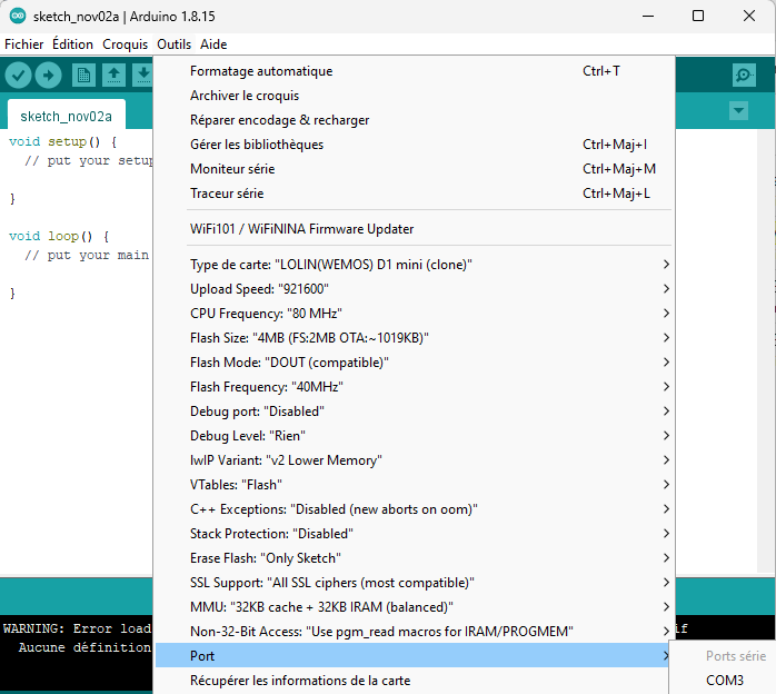
In Arduino, choose the COM port that corresponds to your little beast:
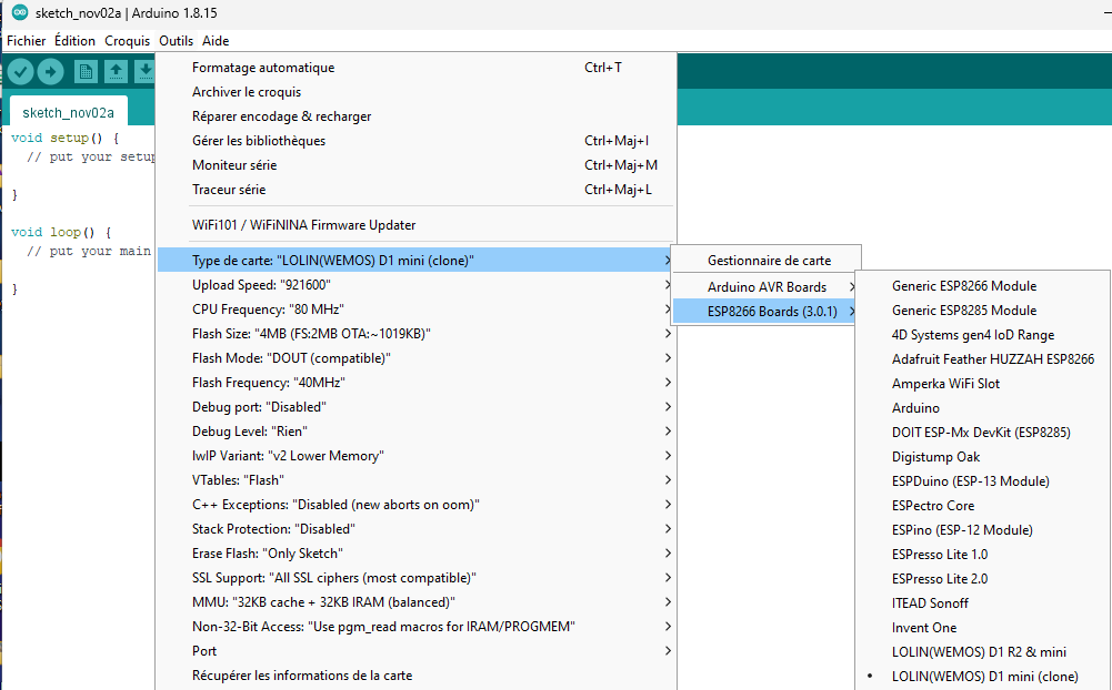
Choose your board (For ESP8266 board copies, I use this board ref:

Programming
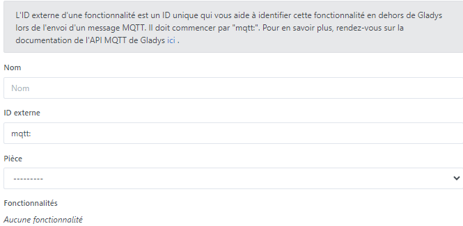
In order for the Gladys buttons to send the values expected by the transmitter, you need to create several MQTT fake devices.
In the MQTT integration, create 2 “fake devices”:
- Shutter control with its 3 buttons that will send the values -1, 0 and 1.
- A dimmer switch that is activated from 2 to 6 inclusive to program and create the interface code between the shutter button and your module.
Indicated Link1 in the code
You can create another text fake device to see in Gladys the command feedback taken into account by the transmitter. It is provided in the code, otherwise put nothing.
Indicated Link2 in the code



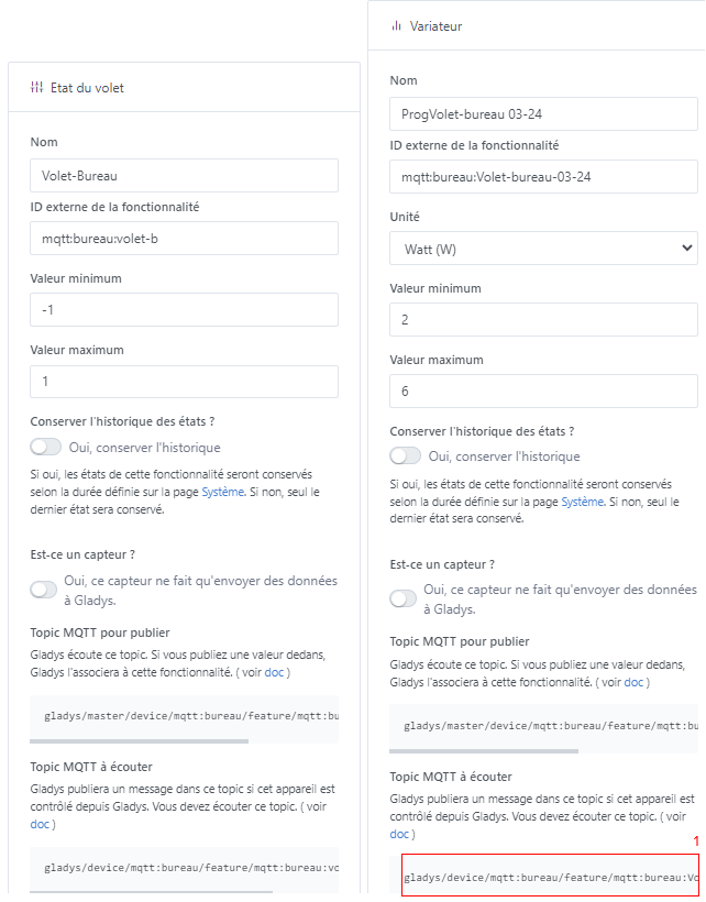
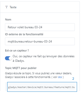
Be sure to get the Topic addresses that you will need to indicate in the code for the ESP8266.
Code:
It probably contains gross errors but I managed to make it run with my limited coding skills. It is therefore very perfectible .. 
I am not the creator of the code, so I do not take the credit. I just adapted it to accept numeric values instead of letters.
2 = Down
3 = Stop
4 = Up
5 = Prog
6 =
The 6 is intentionally left blank to perform the programming with the original command.
If you want to create multiple remote controls or if you need to re-register after modification, remember to increment this value as indicated in the example for each of the transmitters: #define REMOTE 0x122000
/* This sketch allows you to emulate a Somfy RTS or Simu HZ remote.

   This is a fork of the original sketch written by Nickduino (https://github.com/Nickduino)

   If you want to learn more about the Somfy RTS protocol, check out https://pushstack.wordpress.com/somfy-rts-protocol/

   The rolling code will be stored in EEPROM, so that you can power the D1 Mini.

   Easiest way to make it work for you:
    - Choose a remote number
    - Choose a starting point for the rolling code. Any unsigned int works, 1 is a good start
    - Upload the sketch
    - Long-press the program button of YOUR ACTUAL REMOTE until your blind goes up and down slightly
    - send 'p' to the serial terminal oder via 'MQTT'
   To make a group command, just repeat the last two steps with another blind (one by one)

   Then:
    - u will make it to go up
    - s make it stop
    - d will make it to go down
    - p sets the program mode
    - you can also send a HEX number directly for any weird command you (0x9 for the sun and wind detector for instance)
*/

#include <EEPROM.h>
#include <ESP8266WiFi.h>
#include <PubSubClient.h>
#include <AsyncElegantOTA.h>

WiFiClient espClient;
PubSubClient client(espClient);

String header;
const char* ssid = "xx";   // <-- Enter your Wifi-SSID
const char* password = "xx";  // <-- Enter your Wifi-Password

const char* mqtt_server = "xx";  // <-- Enter the IP of your MQTT-Server
const unsigned int mqtt_port = 1883;
const char* mqtt_user =   "xx";
const char* mqtt_password =   "xx"; // <-- Enter the Password of your MQTT-Server
String clientId = "Awning";

// MQTT topic parameters
const char* topic = "link1"; // <-- The topic with encrypted code
const char* topic2 = "link2"; // <-- The command return text topic

#define SYMBOL 640
#define UP 0x2
#define STOP 0x1
#define DOWN 0x4
#define PROG 0x8
#define EEPROM_ADDRESS 0
#define REMOTE 0x121000    //<-- Change it to a unique no., if you have more than one Remote (0x121305, 0x121306, 0x121307, ...)

AsyncWebServer server(80);

char demand = '6'; // w = waiting

const int transmitPin = D1;

unsigned long rollingCode = 1;

byte frame[7];
byte checksum;


void BuildFrame(byte *frame, byte button) {
  unsigned int code;
  EEPROM.get(EEPROM_ADDRESS, code);
  frame[0] = 0xA7; // Encryption key. Doesn't matter much
  frame[1] = button << 4;  // Which button did  you press? The 4 LSB will be the checksum
  frame[2] = code >> 8;    // Rolling code (big endian)
  frame[3] = code;         // Rolling code
  frame[4] = REMOTE >> 16; // Remote address
  frame[5] = REMOTE >>  8; // Remote address
  frame[6] = REMOTE;       // Remote address

  Serial.print("Frame         : ");
  for(byte i = 0; i < 7; i++) {
    if(frame[i] >> 4 == 0) { //  Displays leading zero in case the most significant
      Serial.print("0");     // nibble is a 0.
    }
    Serial.print(frame[i],HEX); Serial.print(" ");
  }

// Checksum calculation: a XOR of all the nibbles
  checksum = 0;
  for(byte i = 0; i < 7; i++) {
    checksum = checksum ^ frame[i] ^ (frame[i] >> 4);
  }
  checksum &= 0b1111; // We keep the last 4 bits only


//Checksum integration
  frame[1] |= checksum; //  If a XOR of all the nibbles is equal to 0, the blinds will
                        // consider the checksum ok.

  Serial.println(""); Serial.print("With checksum : ");
  for(byte i = 0; i < 7; i++) {
    if(frame[i] >> 4 == 0) {
      Serial.print("0");
    }
    Serial.print(frame[i],HEX); Serial.print(" ");
  }


// Obfuscation: a XOR of all the bytes
  for(byte i = 1; i < 7; i++) {
    frame[i] ^= frame[i-1];
  }

  Serial.println(""); Serial.print("Obfuscated    : ");
  for(byte i = 0; i < 7; i++) {
    if(frame[i] >> 4 == 0) {
      Serial.print("0");
    }
    Serial.print(frame[i],HEX); Serial.print(" ");
  }
  Serial.println("");
  Serial.print("Rolling Code  : "); Serial.println(code);
  EEPROM.put(EEPROM_ADDRESS, code + 1); //  We store the value of the rolling code in the
                                        // EEPROM. It should take up to 2 adresses but the
                                        // Arduino function takes care of it.
 EEPROM.commit();
}


void SendCommand(byte *frame, byte sync) {
  if(sync == 2) { // Only with the first frame.
  //Wake-up pulse & Silence
    digitalWrite(transmitPin, HIGH);
    delayMicroseconds(9415);
    digitalWrite(transmitPin, LOW);
    delayMicroseconds(89565);
  }

// Hardware sync: two sync for the first frame, seven for the following ones.
  for (int i = 0; i < sync; i++) {
    digitalWrite(transmitPin, HIGH);
    delayMicroseconds(4*SYMBOL);
    digitalWrite(transmitPin, LOW);
    delayMicroseconds(4*SYMBOL);
  }

// Software sync
  digitalWrite(transmitPin, HIGH);
  delayMicroseconds(4550);
  digitalWrite(transmitPin, LOW);
  delayMicroseconds(SYMBOL);


//Data: bits are sent one by one, starting with the MSB.
  for(byte i = 0; i < 56; i++) {
    if(((frame[i/8] >> (7 - (i%8))) & 1) == 1) {
      digitalWrite(transmitPin, LOW);
      delayMicroseconds(SYMBOL);
      digitalWrite(transmitPin, HIGH);
      delayMicroseconds(SYMBOL);
    }
    else {
      digitalWrite(transmitPin, HIGH);
      delayMicroseconds(SYMBOL);
      digitalWrite(transmitPin, LOW);
      delayMicroseconds(SYMBOL);
    }
  }

  digitalWrite(transmitPin, LOW);
  delayMicroseconds(30415); // Inter-frame silence
}


void callback(char* topic, byte* payload, unsigned int length) {
    if (strcmp(topic,"link1") == 0) {
      char demand_str[length + 1];
      strncpy (demand_str, (char*)payload, length);
      demand_str[length] = '\0';
      Serial.println(demand_str);

      // u = up, d = down, s = stop, p = program, w = wait

      if (strcmp(demand_str,"4") == 0) {
        demand = '4';
      } else if (strcmp(demand_str,"2") == 0) {
        demand = '2';
      } else if (strcmp(demand_str,"3") == 0) {
        demand = '3';
      } else if (strcmp(demand_str,"5") == 0) {
        demand = '5';
      } else {
        demand = '6';
      }
      Serial.println(demand_str);
      Serial.println(demand);
    }
}

void setup() {
  Serial.begin(115200);
  Serial.println(" ");
  Serial.println("Starting Somfy");
  Serial.println();
  Serial.print("Connecting to ");
  Serial.println(ssid);
  WiFi.mode(WIFI_STA);
  WiFi.begin(ssid, password);
  WiFi.hostname("Box-Somfy");

  while (WiFi.status() != WL_CONNECTED) {
    delay(500);
    Serial.print(".");
  }
  Serial.println("");
  Serial.println("WiFi connected");

  Serial.println(WiFi.localIP());

  pinMode(transmitPin, OUTPUT); // Pin D1 on the Wemos D1 mini
  digitalWrite(transmitPin, LOW);

  client.setServer(mqtt_server, mqtt_port);
  client.setCallback(callback);

  server.on("/", HTTP_GET, [](AsyncWebServerRequest *request) {
  request->send(200, "text/plain", "Hi! I am a Wemos D1 mini.");
  });

  AsyncElegantOTA.begin(&server);    // Start ElegantOTA
  server.begin();


  EEPROM.begin(4);
  EEPROM.get(EEPROM_ADDRESS, rollingCode);

  Serial.println(" ");
  Serial.print("Simulated remote number : ");
  Serial.println(REMOTE, HEX);
  Serial.print("Current rolling code    : ");
  Serial.println(rollingCode);
}

void reconnect() {
  // MQTT broker reconnection loop
  while (!client.connected()) {
    Serial.println("Attempting MQTT connection...");
    if (client.connect("WemosClient", mqtt_user, mqtt_password)) {
      Serial.println("Connected to MQTT");
      // MQTT topic subscription
      client.subscribe(topic);
    } else {
      Serial.print("Failed, rc=");
      Serial.print(client.state());
      Serial.println(" Retrying in 5 seconds...");
      delay(5000);
    }
  }
}

void loop() {
  AsyncElegantOTA.loop();

// Check connection to the MQTT broker
  if (!client.connected()) {
    reconnect();
  }
  // Update MQTT client
  client.loop();

  if (demand == '4' || demand == '2' || demand == '3' || demand == '5') {

//    char serie = (char)Serial.read();
    char serie = (char)demand;
    if(serie == '4') {
      demand = '4';
      Serial.println("up"); // Somfy is a French company, after all.
      BuildFrame(frame, UP);

      client.publish(topic2, "up");
      delay(50);
      client.subscribe(topic2);
      Serial.println("moving up");
    }
    else if(serie == '2') {
      demand = '2';
      Serial.println("down");
      BuildFrame(frame, DOWN);
      client.publish(topic2, "down");
      delay(50);
      client.subscribe(topic2);
      Serial.println("moving down");
    }
    else if(serie == '5') {
      demand = '5';
      Serial.println("prog");
      BuildFrame(frame, PROG);
      client.publish(topic2, "prog");
      delay(50);
      client.subscribe(topic2);
      Serial.println("prog mode");
    }
    else if(serie == '3') {
      demand = '3';
      Serial.println("stop");
      BuildFrame(frame, STOP);
      client.publish(topic2, "stop");
      delay(50);
      client.subscribe(topic2);
      Serial.println("stop");
    }

    demand = '6';

    Serial.println("");
    SendCommand(frame, 2);
    for(int i = 0; i<2; i++) {
      SendCommand(frame, 7);
    }
  }
}
Consider changing these values according to your own installation:
• const char* ssid = « your SSID network name »;
• const char* password = « your Wi-Fi code »;
• #define MQTT_BROKER « broker IP address »
• #define MQTT_BROKER_PORT 1883
• #define MQTT_USERNAME « MQTT broker username »
• #define MQTT_KEY « broker password »
If you use this code for multiple modules on the same MQTT broker, consider changing this value in the « void reconnect » section:
if (client.connect(« WemosClient2 », mqtt_user, mqtt_password)) {
Gladys Scenes:
Finally, to work with Gladys’ new alarm system, you need to create 3 scenes for controlling the shutter based on this one:
Lower shutter: -1 → 2
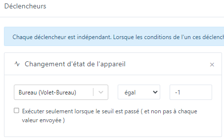
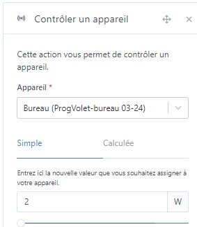
Same for Stop: 0 → 3
Same for Raise: 1 → 4
Recording the new module on the shutter.
Last step, put the shutter in new remote control recording mode. You should have a programming button on your remote that you need to press for a few seconds. The shutter should go up and down a bit to confirm.
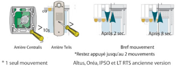
In Gladys, set the dimmer to 5. The shutter should react and repeat the movement.
If yes, that’s it 
Otherwise, try again by switching the dimmer to 6 then 5. It may be necessary to change the code for the shutter to interpret this as a new remote control.
The shutter exits remote control recording mode on its own.
Good luck.
Tiboys


