Hello,
I am not modifying the tutorial to keep the history. I am making an important update:
As of today, September 20, 2024, NODE_RED has evolved and is now version 4.0, and node-red-node-serialport is version 2.0.3
The version of node-red integrated with Gladys is 3.1.15, and node-red-node-serialport is version 2.0.3
We no longer need to downgrade the version of node-red-node-serialport to 0.15.0
Version 2.0.3 works very well with Rflink, so we can skip
the paragraph « revert to version 0.15.0 » of node-red-node-serialport
Here is a tutorial on how the RFLINK gateway works with Node Red and Gladys.
Note, this chapter is added following the upgrade of NODE RED to V3, and also includes the downgrade of the Serialport palette v1.0.1 which should not be used.
If you already have a NodeRed that no longer works, you need to uninstall it, otherwise go directly to the installation..
Tutorial to reinstall NODE Red in V3 and keep version 0.15.0 of Serialport
- Switch to V3 of node red in June 2022
- Switch to version 1.0.1 of serial port in March 2022
caused disruptions in the operation of the rflink.
As of now (early March 2022), the node-red-node-serialport palette has been updated and this update crashes node red with the following error message:

A big thank you to @VonOx for guiding me so patiently.
The installation command in this video no longer works following the switch to V3 of Node Red. You then need to replace it with the following commands:
: Integrate Node-RED with Gladys Assistant in MQTT | Gladys Assistant
Uninstall the old node red
1 - stop the docker container
docker stop node_red
2 - remove the node red container
docker rm node_red
3 - delete the node-red folder in \var\lib
cd /var/lib
4 - we are in the lib folder, display the folder contents
ls
5 - look for the node-red folder (watch out for the dash 6) and delete it:
sudo rm -r node-red
6 - verify that the node-red folder is no longer there
ls
7 - return to the pi@gladys:~ $ prompt
cd /
8 - I reboot the rpi (I don’t know if it’s useful but it reassures me)
sudo reboot
9 - Verify that the node red container is no longer there
docker ps
Installation of node red
1 - type the command of @VonOx, you will need a system connected to the USB0 and USB1 ports, for my part I have an RFlink on the ttyUSB0 port and the Sonoff zigbee key on the ttyUSB1 port. So you may need to adapt in the lines " --device=/dev/ttyUSB0 \ " the name of the port used may be ttyACM0.
docker run -d \
--log-opt max-size=10m \
--restart=always \
--network=host \
--name node_red \
-u node-red:dialout \
--device=/dev/ttyUSB0 \
--device=/dev/ttyUSB1 \
--label com.centurylinklabs.watchtower.enable=false \
-v /var/lib/node-red:/data \
nodered/node-red
Note, you will need to adapt the line:
--device=/dev/ttyUSB0 \
Depending on the USB port where the RFlink is connected, sometimes the RFlink may be connected to the USB port: /dev/ttyAMA0.
In my case, /devttyUSB0 corresponds to my zigbee key and /dev/ttyUSB1 corresponds to my RFlink
Note with this command line:
--label com.centurylinklabs.watchtower.enable=false \
Watchtower no longer updates Node red and when you restart the PI, node red no longer starts automatically like Gladys. You will need to restart the node red container with « docker restart node_red »
2 - then this one
sudo chown -R 1000:1000 /var/lib/node-red
3 - Generate a hash: For more precision, watch Pierre-Gilles’ video: Integrate Node-RED with Gladys Assistant in MQTT | Gladys Assistant
Generate a hash
docker exec -it node_red node-red admin hash-pw
example of hash: $2b$08$tfrMEc4pnblhhSDFFBUjeOtGU.Ixh5d19P31NWCf2JZKmwZF888mK
4 - Edit the file with nano: Do not forget Sudo (in front for me it is necessary)
sudo nano /var/lib/node-red/settings.js
Remove the double / between "adminAuth: " and the corresponding closing brace }
5 - Paste the generated hash
6 - Then restart node red
docker restart node_red
Downgrade the version of Serialport
we will use version 0.15.0 instead of version 1.0.1
thanks to [bjm] for his tutorial
So you need to keep the version node-red-node-serialport 0.15.0. To retrieve this version, you need to follow the tutorial of @Bjm, which I will paste below
I installed node-red-node-serialport version 0.15.0 which worked on my 32 bits
https://www.npmjs.com/package/node-red-node-serialport/v/0.15.0
1 - In the terminal to open a Shell in docker
docker exec -it node_red /bin/bash
This returns to me
bash-5.0#
2 - I copy the following command at the end
npm i node-red-node-serialport@0.15.0
This processes and at the end returns this to me
notice created a lockfile as package-lock.json. You should commit this file.
+ node-red-node-serialport@0.15.0
added 48 packages from 37 contributors and audited 338 packages in 60.866s
45 packages are looking for funding
  run `npm fund` for details

found 4 critical severity vulnerabilities
  run `npm audit fix` to fix them, or `npm audit` for details
3 - As there are 4 critical vulnerabilities I do
npm audit fix
As suggested
4 - Then
exit
5 - restart node red
docker restart node_red
RFlink design
I use a homemade RFlink (see link to build one: http://domo-attitude.fr/montage-et-la-programmation-de-votre-rflink/). APPEARANTLY THIS LINK IS DEAD
New link:
DOKU188: Platform Opendomotech APK Situs Slot Gacor Slot88 & Slot777 Terpercaya
For the antennas, I only use two pieces of wire and it works very well (however, the transmitter’s antenna must measure exactly 17.2cm (a matter of frequency).
Table of contents:
RFlink and Node Red: Reception
1 Connect the RFlink.
2 Install the « palette: node-red-node-serialport »
3 Install nodes to receive frequencies
4 Visualize the received information
5 Detail of the RFlink reception code
6 Sorting through the received information
RFlink and Node Red: Transmission
1 Explanation of the frame structure of a transmitted command
2 Let’s test the frame.
RFlink and Node Red: Reception
1. Connect the RFlink.
Connect the RFlink to a USB port on the RPI
Type the command “dmesg -s 1024”, using PuTTY, to find the address of the USB port it is connected to
After executing the command, you can read this on the last line:
[69837.733913] ch341 1-1.2:1.0: ch341-uart converter detected
[69837.736457] usb 1-1.2: ch341-uart converter now attached to ttyUSB0
If it didn’t work, unplug and replug the RFlink and start the procedure again at 1.
Here, the RFlink is connected to the port: ttyUSB0 (to be retrieved and written in the configuration of the « Receiver Node »).
2. Install the « palette: node-red-node-serialport »
Open Node RED to install the palette « node-red-node-serialport »
Click on the three horizontal bars in the top right to open the menu above.
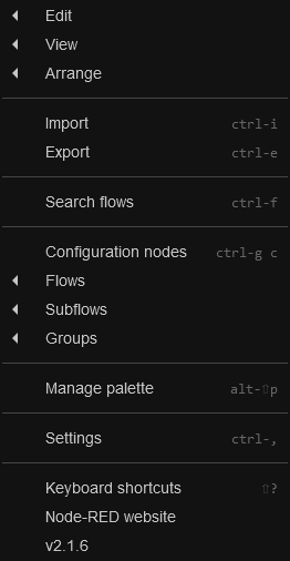
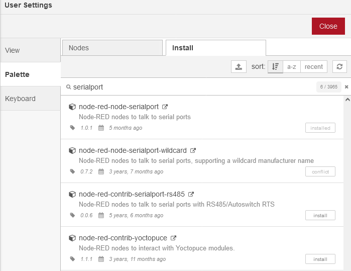
Click on « manage palette » in the 11th line. The window below opens, click on the « install » tab, then type « serial » in « search modules » to search for palettes (libraries). Libraries are displayed. We will choose the library (or palette) « node-red-node-serialport » (at the beginning of the tutorial, we configured to retrieve version 0.15.0 of serialport, but in manage palette, version 1.0.1 appears, you need to install it and it is at the time of verification that you see that you have indeed installed version 0.15.0 of SerialPort), click on the small « install » on the right.
Once done, click on the Nodes tab.
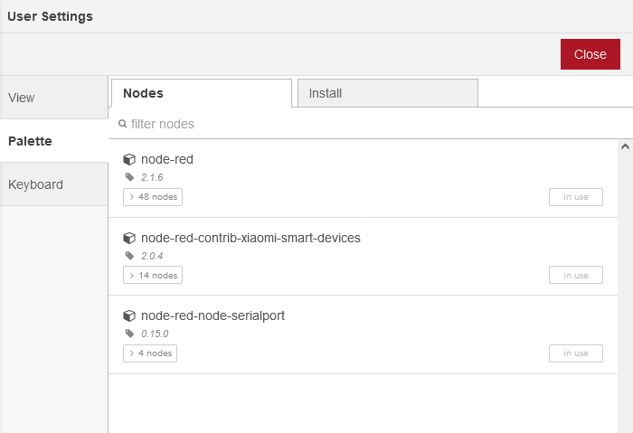
Check that the palette is indeed there in version 0.15.0. Then check in the « filters nodes » column on the left side of the screen that you have the following nodes:
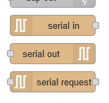
3. Install nodes to receive frequencies:
We drag to the center of the screen the « node Serial in » and a « node debug » to start. We connect them by clicking/dragging from the small circle of the « receiver node » to the small circle of the « node debug(msg.payload) »

Configuration of the « Receiver Node »
We double-click on the « node serial in », in the image called « receiver »
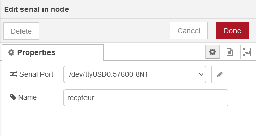
Then we click on the small pencil
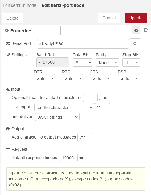
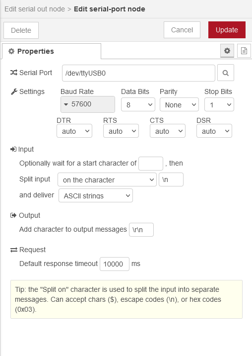
So in the « Serial Port » box, we write the name of the USB port that we found in chapter 1 in the form " /dev/ttyUSB0". Here the RFlink is connected to USB0. You also need to fill in the « Output » box with « /r/n », very important for the transmitter part. Then, you need to click on Update in the top right to save the changes.
This takes us back to the previous screen, we see that the « Serial Port » box is filled, all that’s left is to give a name to the Node, by writing the name you want in the « Name » box, I put receiver, that’s why my « node serial in » is displayed « receiver ».
Once you’re done, click on « Done », the window closes.
Remark:
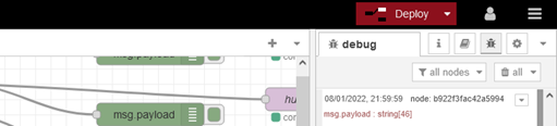
Every time you create, modify, or move a node, the « deploy » lights up red to indicate that you need to click on it, a kind of validation.

Here the « Node Debug » has a small blue circle because it has not been validated after modifications, so we « Deploy » and the small blue circles disappear. Under the « receiver node », there is a small green square indicating that the node is connected to the RFlink.
<
4. Visualization of the received information
So if we have all these conditions met (connected and « deploy » on black background), we should see information appearing in the Debug window.
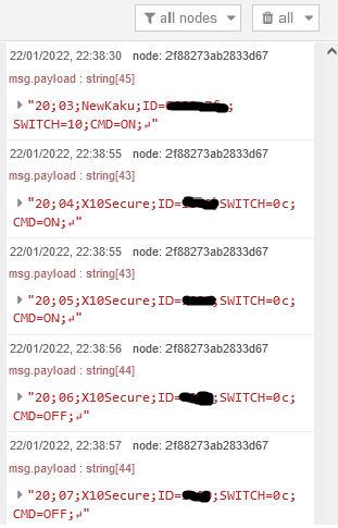
If you don’t have this window, maybe you have the window below
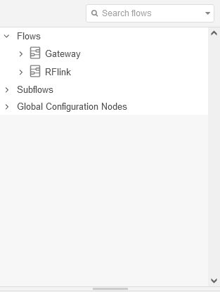
If so, you will then need to click on the little bug (that’s just me), to get to the Debug window.
In this window, all the information from the sensors received at 433MHz (if RFlink is at 433MHz) is displayed. If you see nothing, it’s probably because you don’t have any sensors emitting at 433MHz around you. Take a 433MHz remote control, click on it and the remote control information should be displayed in the « debug » window.
In the window above, the first information received
20;01;NewKaku;ID=xxxx;SWITCH=10;CMD=ON;
This is an On command that I sent with a connected plug remote control.
The following information:
twice
20;01;X10Secure;ID=xxxx;SWITCH=0c;CMD=ON;
then twice
20;01;X10Secure;ID=xxxx;SWITCH=0c;CMD=OFF;
This is an X10 infrared sensor that sends this information. Here, the ON « CMD=ON » and then OFF « CMD=OFF » commands are received, which mean that there has been a detection.
5. Detail of the RFlink reception code (notice RFlink, everything is there: RFLink Gateway - HomeAutomation )
Structure of the RFlink command in the case of received data:
Data: 20;02;Name;ID=9999;LABEL=data;
Fields: 20 => Node number 20 means that the direction of the dialogue flows from the RFlink Gateway to the Rpi, (and Node 10 means that the direction of the dialogue flows from the Rpi to the RFlink Gateway, used for the transmission of the 433MHz signal)
; => field separator
02 => packet counter (from 00-FF)
NAME => Name of the device (can be used to display in applications, etc.)
ID=9999 => Device ID (often a rotating code and/or a channel number of the device) (Hexadecimal)
SWITCH=A16 => House/unit code like A1, P2, B16 or a button number etc.
CMD=ON => Command (ON/OFF/ALLON/ALLOFF).
6. Sorting through the received information
Warning from here on, you will need to adapt your codes according to your sensors and their parameters
But among all the information received by the RFlink, you need to sort out the ones that interest you. So, we add a « Node function » for selection and then to send the info to Gladys we need a « Node Mqtt » and we connect them together. We « Deploy » to validate, the blue points disappear. The two « nodes msg.payload » extract the information after processing by the nodes and send it to the debug window. If you click on the square of a msg.payload, which is on the right of the node, it enters the node and has the effect of no longer displaying its message (information) in the debug window. Click on it again to restore the display.

Configuration « Node function »:
We click twice on the « Node function » to open it. We give it a name in the « Name » box and in the « On Message » tab, we will write the code (or copy it)
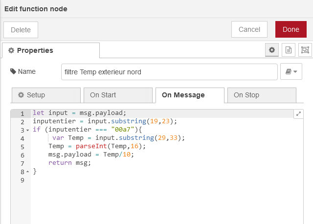
Explanation of the code:
Simply: in the msg.payload line 1, you find the value transmitted by the previous Node (here it’s « Node receiver »), in line 6 of the code you reload a value into msg.payload, with the « return msg » in line 7, you send the msg.payload to the next node (here « Node Mqtt » and at the same time to the « Node debug »).
In the msg.payload of line 1, you find the information that arrives in real-time in the « debug window », which we saw previously. You will need to sort the command you want to transmit to Gladys (we take the example of a temperature sensor that sends its info: "20;07;Mebus;ID=ea01;TEMP=0017; ").
(I found this way of doing things, but there must surely be others).
I count the relevant characters to retrieve a single string in order to sort. I will look for the characters of the sensor ID here
Line 1: we store the msg.payload (captured information) in the variable input,
Line 2: we will retrieve the device ID (ea01), by counting the characters of the string "20;07;Mebus;ID=ea01;TEMP=0017; ", with the function « Substring (xx,xx) », (we start counting from 0), here we need to retrieve from the 15th to the 19th characters. We will write « Substring (15,19) ». We already make a first sort on the device. We then filter out the other devices, since they do not have the same ID.
Line 3: we apply the same method, but this time, we retrieve the value of the data to be processed (here temperature). Substring(25,29). Note: we will count one more character to be able to retrieve the 7 of 0017, if we write Substring(25,28), 28 being the 7, we will only retrieve 001, to retrieve the 7 we need to count up to the 29th character, as previously for the 1 of the ID.
Line 4: we place the string of characters in the variable « Temp » (the string corresponds to the 25th to 29th character)
Line 5: we convert the « temp » value from hexadecimal to decimal
Line 6: we load the Temp value into msg.payload, but before we divide it by 10, because my sensor sends a value 10 times larger.
Line 7: sending msg.payload to the next node. (Note that the line of code « return msg » is in the if condition. This is to send the msg.payload only if it is the device corresponding to the ID=« ea01 », if the « return msg » is outside the If, that is to say after « } », it will be sent every time the « node receiver » receives information passed by different sensors.
I give you the code to paste but you will have to adapt it to your case. You need to retake the character count and modify the « ID 00a7 ».
Code to copy:
let input = msg.payload;
inputID = input.substring(19,23);
if (inputID === "00a7"){ // replace "00a7" with the ID of your sensor
var Temp = input.substring(29,33);
Temp = parseInt(Temp,16);
msg.payload = Temp/10;
return msg;
}
You will find the code to manage a negative temperature, the explanations are in the comments in this code.
Thanks to @gaetanb76 (for his suggestion and especially his code)
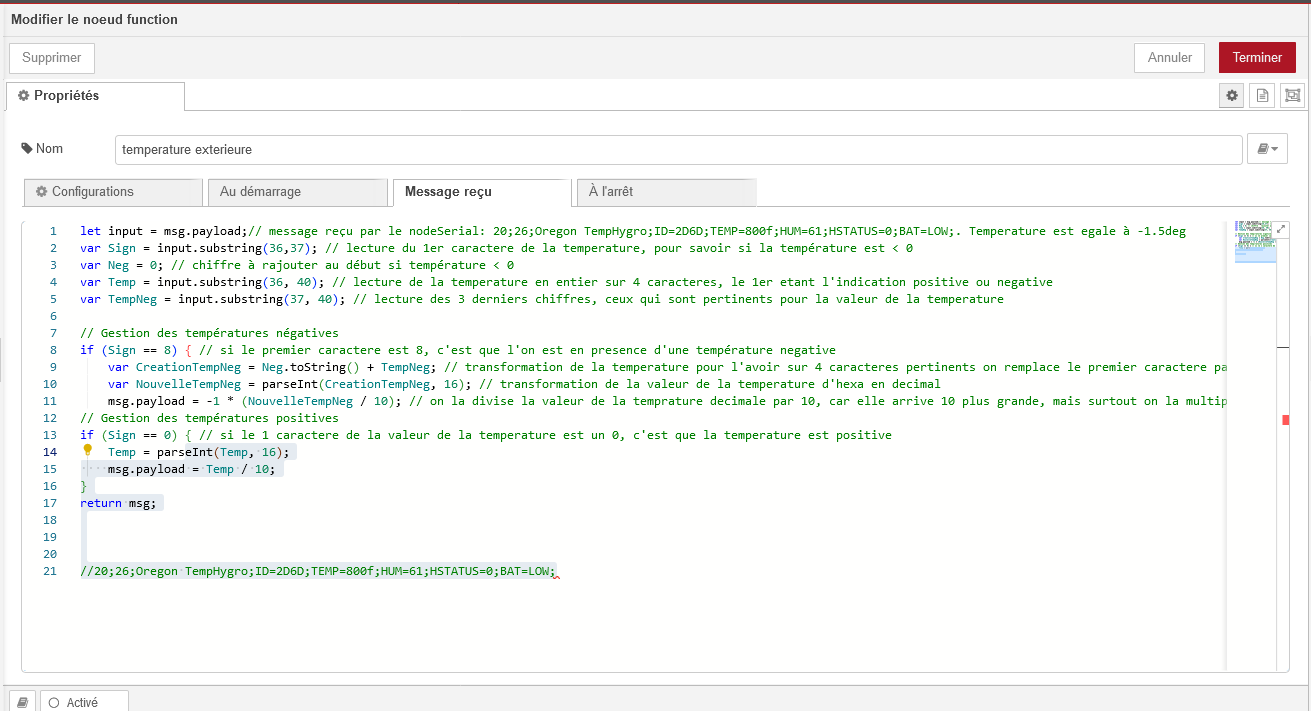
Code to copy:
let input = msg.payload; // message received by the Serial node; example: 20;26;Oregon TempHygro;ID=2D6D;TEMP=800f;HUM=61;HSTATUS=0;BAT=LOW; . Temperature is equal to -1.5deg
var Sign = input.substring(36,37); // read the first character of the temperature, to know if the temperature is < 0
var Neg = 0; // digit to add at the beginning if temperature < 0
var Temp = input.substring(36, 40); // read the temperature as a whole on 4 characters, the first one being the positive (0) or negative (8) indication
var TempNeg = input.substring(37, 40); // read the last 3 digits, those that are relevant for the temperature value

// Managing negative temperatures
if (Sign == 8) { // if the first character is 8, it means we are dealing with a negative temperature
var CreationTempNeg = Neg.toString() + TempNeg; // transformation of the temperature to have it on 4 relevant characters; we replace the first character with a 0
var NouvelleTempNeg = parseInt(CreationTempNeg, 16); // transformation of the temperature value from hex to decimal
msg.payload = -1 * (NouvelleTempNeg / 10); // we divide the decimal temperature value by 10, because it arrives 10 times larger, but above all we multiply it by *-1 to make it negative
}
// Managing positive temperatures
if (Sign == 0) { // if the first character of the temperature value is a 0, it means the temperature is positive
Temp = parseInt(Temp, 16);
msg.payload = Temp / 10;
}
return msg;
7. Creating the MQTT Node
Setting up the « Node Mqtt »:
Pierre Gilles, in his Node Red video, advises creating the device in Gladys first, which allows you to already have the name of the MQTT topic when you set up the « Node Mqtt » in Node Red, for the tutorial I do it by following the description of the Nodes. If this has not been done, drag the « Node Mqtt out » onto the screen and connect it to the node that precedes it (the Function node).
On the Gladys side,
You now need to create the sensor in the MQTT integration in Gladys.
Once created, you need to retrieve: the broker address (Broker URL), the MQTT server name (username) and the Password
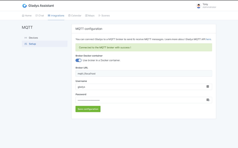
You also need to note the « MQTT Topic » of the sensor,
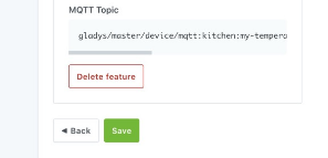
On the Node Red side:
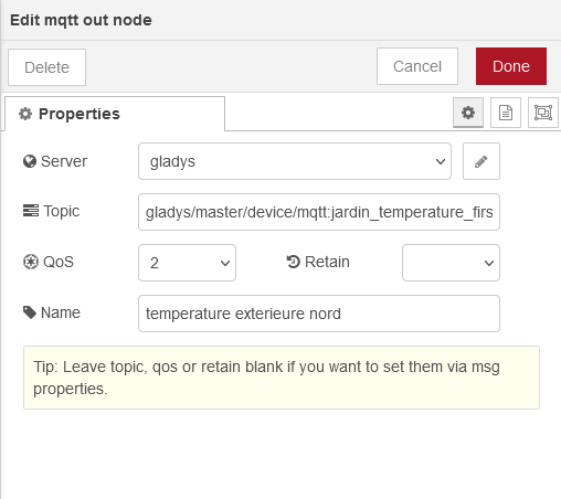
Double-click on the « node Mqtt out » noted « filter external north temp »

If the Gladys broker is not already declared, you need to configure it, click on the small pencil
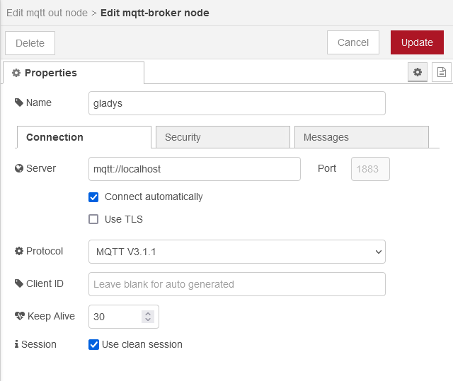
Then click on the « Security » tab
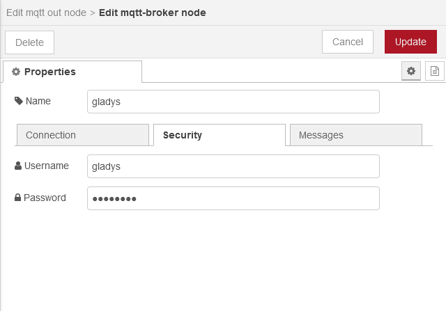
Fill in the « Username » and « Password » fields with the values retrieved from Gladys Mqtt.
Click on the « Connection » tab
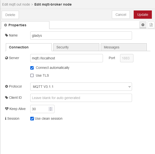
In the « Server » field, if it is not filled in, note the IP address of the MQTT Broker, or if it is declared in Gladys note « mqtt://localhost »
Click on Update to save.
Return to the previous window
Normally the « Server » field is filled in with the name entered in « Username » previously.
In the Topic field, you need to copy or write the name of the topic, created by Gladys, when creating the sensor or the sensor function.
Give a name to the Node, in the « Name » field.
Write in the QoS 0, 1 or 2
QOS 0 – sends the message once (not guaranteed)
QOS 1 – At least once (guaranteed)
QOS 2 – Only once (guaranteed)
Click on « Done » to save
If everything is correct, after a few seconds, after « Deploy », you should have the « small green square connected » displayed under the node
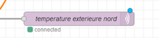
If you have displayed the sensor in the Gladys dashboard, you should have a value that appears on this sensor.
RFlink and Node Red: Transmission
Now let’s move on to sending commands via the Gladys Dashboard and Mqtt.
In the RFlink documentation (see link at the beginning of the tutorial), it is written:
« To respond to RFlink to emit RF commands or to make changes to the parameters, a line of text must be sent, which ends with CR/LF. »
I spent a few hours trying to understand how to send this CR/LF (in French in the text return carriage and line feed) and all that, it had to be pasted at the end of the command issued. Until the moment I understood that this happened in the declaration of the Serial Port. Remember the small \r\n, in the « Output » field, line « Add character to output message ». On the command confirmations, received and valid, we will see the CR/LF materialized by a small arrow (which returns to the left), in the Debug window.
1. Explanation of the frame structure of a command issued:
When you press the button on a connected plug remote control, you see the code that RFlink receives appear in the Debug window, such as: « 20;06;NewKaku;ID=008440e6;SWITCH=a;CMD=OFF; ». To send the same command with Gladys via Mqtt to the same connected plug, you will need to modify this received code into a code that RFlink can emit to this connected plug.
We will first tell RFlink that it needs to emit this code. Therefore, the beginning of the frame will start with « 10; » instead of « 20;06; » which is for reception.
Then we will add the device name « NewKaku; », which signals to RFlink what encoding it will find.
Then we simply write the values of the fields without their names, « ID=008440e6; » becomes « 008440e6 », « SWITCH=a » becomes « a » and so on.
To end up with this frame, without forgetting the semicolons:
10;NewKaku;008440e6;a;OFF;
2. Let’s test the frame:
To start, we will install the Nodes,
We need:
-an « node mqtt in »
-two « nodes change »
-the main node « node serial out »
and finally some « nodes debug »

We drag them onto the Node Red screen, then connect them together as in the image.
Node Configuration
The « mqtt in » Node.
You need to create a device in Gladys Mqtt integration, we will install an LED strip connected to a connected plug, with an On/Off Lighting function. (See: Declare an MQTT device in Gladys. Follow this link: « MQTT | Gladys Assistant »
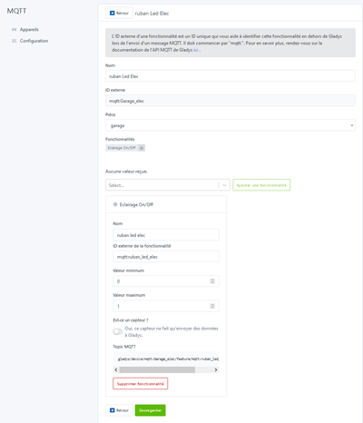
Once done, we save and copy the « MQTT Topic » box.
In Node Red, we double-click on the « Node mqtt in »
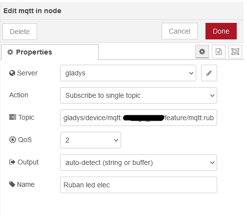
We select the Mqtt broker, in the Server box here the Mqtt broker installed with Gladys and we fill in the « Name » box to give a name to the « mqtt in » Node.
The « change » Node:
As the values sent by the Gladys Mqtt device are only « 1 » and « 0 », we will change these values into a frame corresponding to the lighting or extinguishing of the LED strip compatible with RFlink.
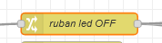
When we want to turn off the LED strip, Gladys Mqtt sends a « 0 » and RFlink wants this frame: « 10;NewKaku;xxxxxxx;a;OFF; » to turn off the LED strip.
Configuration of the « Node change OFF »
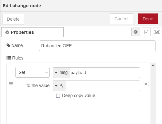
Fill in:
Name: node name
In the « Set » box, unfold the menu by clicking on the small arrow, and click on « change ».

Fill in with your frames: « search for » corresponds to the state « 0 » sent by Gladys Mqtt and in « Replace with » write the LED strip turn-off command. When this node receives a « 0 » on its input, it sends the frame: « 10;NewKaku;008440e6;a;OFF; » on its output. AND if it receives anything other than « 0 » it sends « 1 ».
Configuration of the « Node change On »
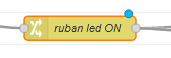
It will be enough to copy/paste the « Node change Off », which allows us to recover all the values that we have already filled in. We modify the « 0 » with a « 1 » and at the end of the frame we replace the « OFF » with the « ON ». And to finish we change its name in « Name ». When this node receives a « 1 » on its input, it sends the frame: 10;NewKaku;008440e6;a;ON; on its output. AND if it receives anything other than « 1 » it sends « 1 ».
The « node debug »
The « Nodes debug » allow you to visualize the values of msg.payload at different points in the sequence.
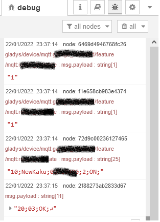
Here is the debug window after an ON command of the LED strip.
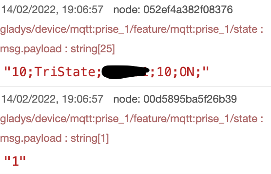
We see the command sent by the ON Node, in the 3rd message and we see in the 4th message, the confirmation from RFlink, that the command is received and valid. (Here we see the CR/LF translated by the small arrow). In the 1st message we see a « 1 » which corresponds to the command sent by Gladys Mqtt and the 2nd message is a « 1 », which is sent by the OFF node.
I hope that wasn’t too hard to read.
The codes can certainly be improved, as I am a beginner in Node Red and in Js, so I am open to all code optimizations. (I’ve already read that somewhere).
If you encounter any problems, I can try to help you.
You have the principle, you can apply it to almost all sensors and switches (remote controls). You will see you will even capture sensors that do not belong to you, if you do not live in the countryside. 
Good luck