If you, like me, have some old plugs or other « connected » accessories from the early days communicating at 433MHz, this might interest you.
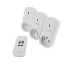
It’s possible to integrate them quite easily into Gladys Assistant using a little inexpensive hardware and give them a second life!
Hardware
You will need to acquire:
-
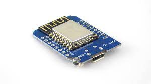
A Wemos D1 Mini ;
-
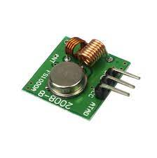
An RF433 transmitter (e.g.: FS1000A) ;
-
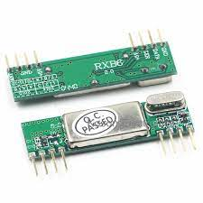
An RF433 receiver (e.g.: RXB6) ;
-
Some Dupont wires/connectors
Assembly
Once the hardware is received, let’s assemble everything!
It is possible to mount all of this without soldering anything but… it’s harder to find the Wemos already soldered!
The data pin of the FS1000a to D2 and the data of the RXB6 to D1. Note that you must provide an antenna if the modules you purchased didn’t include one. How to do it? Simply attach a 17.5 cm wire to the connection point provided for this (ant)!
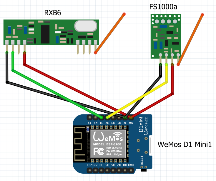
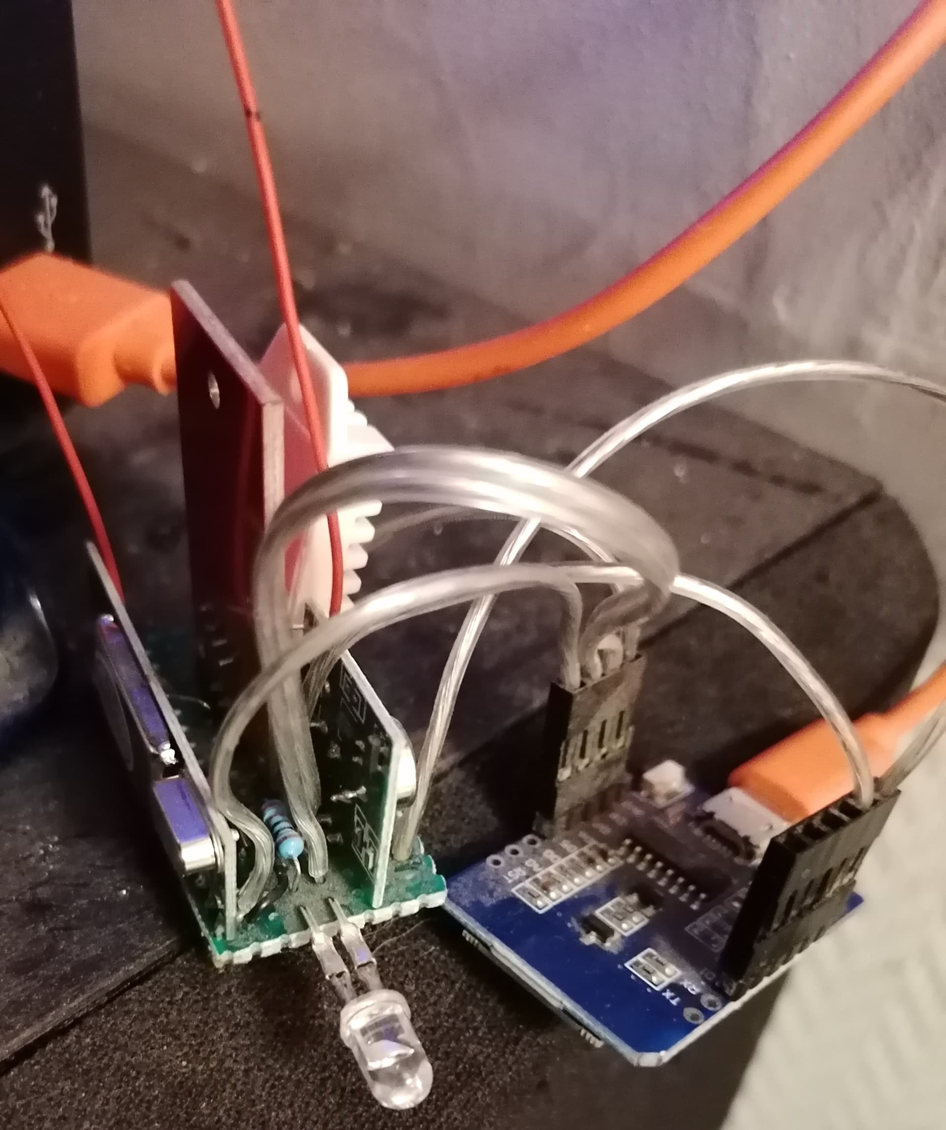
General assembly:
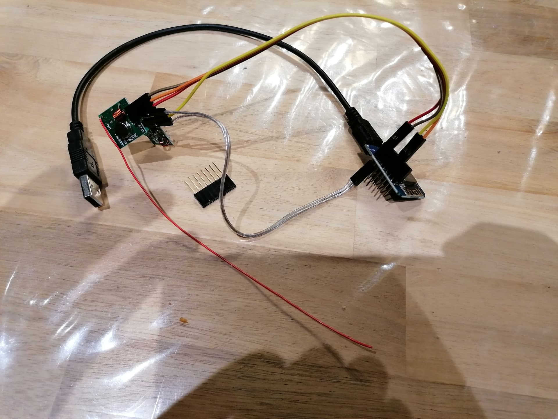
Top view:

The transmitter:

Side view:
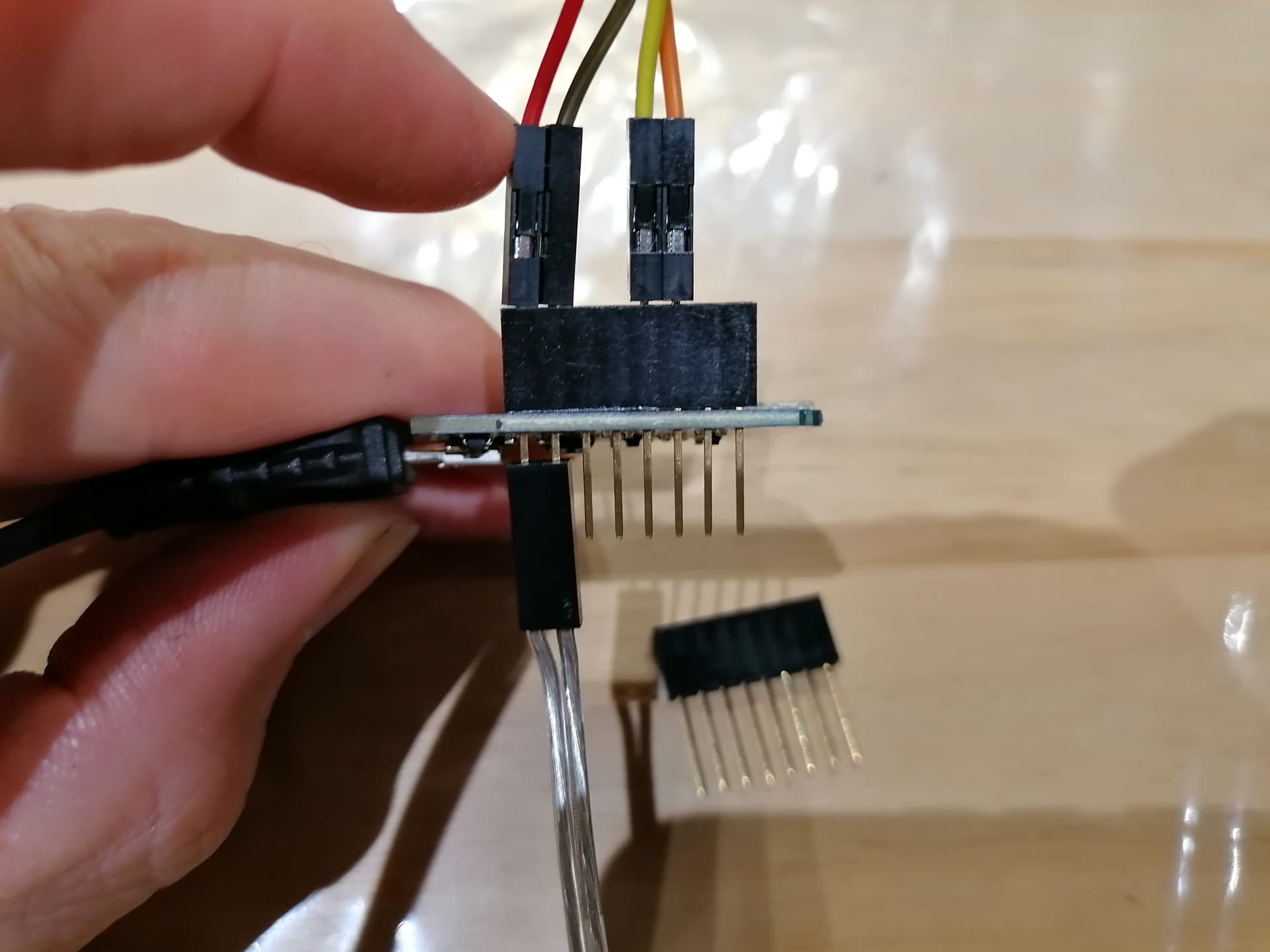
If you look closely, I’m using a Dupont connector (supplied with the Wemos) that allows you to plug in from the top and bottom at the same time, avoiding any soldering.
My final assembly (with an infrared LED and a DHT22 sensor (temperature) in addition):
Preparation
We will install (flash) Tasmota on the Wemos D1 Mini.
To do this, nothing could be simpler (on Windows):
-
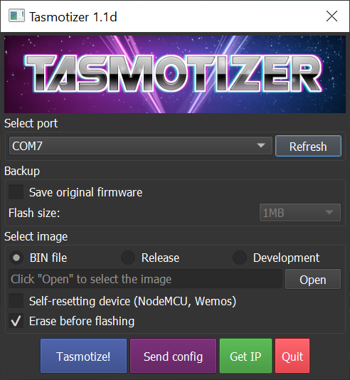
Download « Tasmotizer »
-
Download the latest Tasmota firmware (Note: you must take the Sensor version!) Direct Link
-
Plug the Wemos into the PC via USB
-
Choose the previous file in the Tasmotizer interface (open), check the « Self-resetting device » and « Erase before flashing » boxes then Tasmotize!

Then, you need to modify the Tasmota configuration to connect to WiFi, MQTT, etc.
Use your smartphone to connect to your new device and connect it to your network.
Search for the new WiFi networks. Connect to the Tasmota-xxxx network that should appear. You should then get a configuration proposal from Tasmota. Enter your WiFi network information.
I won’t detail the procedure here because other topics already cover it.
Wemos Configuration
On the Wemos Tasmota homepage, click Configuration > Configure Other and paste the following code into the Template field:
{"NAME":"Wemos D1","GPIO":[1,1,1,1,1,1,1,1,1,1,1,1,1,1],"FLAG":0,"BASE":18}
Check the Activate box then Save.
After the Wemos restarts, click Configuration > Configure Module and select the boxes as shown below:
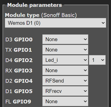
And click Save. Keep the Tasmota page handy, we’ll need it again!
Go back to Gladys:
- MQTT Integration
- New device
I recommend « Integer Counter » (« Compteur entier ») but it doesn’t really matter…
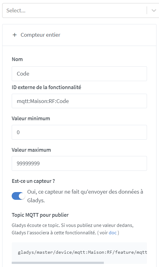
And there, copy the MQTT Topic to publish
Return to the Tasmota page from earlier:
Choose « Console »
Paste the MQTT Topic to publish copied earlier into the following string, in place of my topic (gladys/master/device/mqtt:Maison:RF/feature/mqtt:Maison:RF:Code/state)
Rule1 ON RfReceived#Data!=0 DO publish gladys/master/device/mqtt:Maison:RF/feature/mqtt:Maison:RF:Code/state %value% ENDON
(So it’s « Rule1 ON RfReceived#Data!=0 DO publish YOUR TOPIC %value% ENDON »)
Press « Enter » then validate the command Rule1 1 to activate the created rule.
That’s it!
Finally, the essential part remains: integrate this into scenes…
What will be the trigger?
The easiest is to collect the codes from remotes and other peripherals recognized by the Tasmota integration. To do this, simply add the device created at the beginning to your Dashboard
![]()
You can then create a trigger like this:

But how to control them then?
Simple!
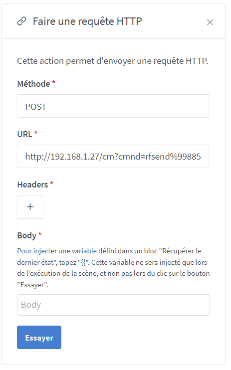
Use the HTTP command « rfsend%20xxxxxx » where xxxxxx corresponds to the code to send directly from scenes! Here’s an example:
http://192.168.1.27/cm?cmnd=rfsend%20998854
Where « 192.168.1.27 » corresponds to the IP address of the Wemos.
And for info, the whole setup can work for infrared too, just by adapting. If interested, I’ll show you ![]()