1. Materials chosen:
- A Wemos D1 Mini (or equivalent Chinese alternative): https://www.aliexpress.com/item/32630518881.html?spm=a2g0s.9042311.0.0.4b7a4c4dQTfFXq;
- An RFID reader: RF522 (almost universal): https://www.aliexpress.com/item/4000029144197.html?spm=a2g0o.productlist.0.0.63901cfaJ5YwjT&algo_pvid=null&algo_expid=null&btsid=0b0a556f16215414175431574e32da&ws_ab_test=searchweb0_0,searchweb201602_,searchweb201603_;
- A 5V power supply (e.g., an old phone charger) and its micro USB cable;
- Some cables (with DuPont connectors if you’re making the solderless version);
- Some solder and an iron (not essential if you opt for slightly more expensive but pre-assembled versions).
2. Preparation
After ordering and receiving (yes, it will arrive!) your materials, you need to program the Wemos D1 Mini. I chose to use Tasmota for its ease of use and scalability, requiring no programming skills!
The only difficulty: RFID reader management is not included in the base program, so you need to compile it! But don’t be afraid… There are two possibilities:
- Either you do it (it’s not complicated at all, see here: https://gitpod.io/#https://github.com/benzino77/tasmocompiler). You need to add the following values in the
user_config_override.hfile:
#define USE_SPI                                  // Hardware SPI using GPIO12(MISO), GPIO13(MOSI) and GPIO14(CLK) in addition to two user selectable GPIOs(CS and DC)
#define USE_RC522                              // Add support for MFRC522 13.56Mhz Rfid reader (+6k code)
#define USE_RC522_DATA_FUNCTION              // Add support for reading data block content (+0k4 code)
#define USE_RC522_TYPE_INFORMATION           // Add support for showing card type (+0k4 code)
- Or you download the one I prepared for you (version 9.4) here
Connect your Wemos D1 Mini to your PC with your USB cable.
Then, download and run « Tasmotizer » (here: https://github.com/tasmota/tasmotizer/releases)
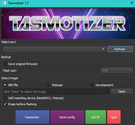
Select, if not done automatically, the « COM » port corresponding to your Wemos, click then on « open », search for the « .bin » file that you just created/downloaded (the Tasmota firmware) then click on « Tasmotize! »
Then, we configure Tasmota. This requires a bit of encoding and copying.
3. Configure Tasmota
3.1 The WiFi
If the flash was successful, you should find a new WiFi network starting with « Tasmota-xxxx ». Connect to it (I recommend doing this with a smartphone!). If your device does not offer it, go to the configuration web page: 192.168.4.1
Enter the necessary information for Tasmota to function (the WiFi network it should connect to and its associated password). The Wemos then restarts and disappears!
You now need to find its IP address to configure it. Two possibilities: explore the network or… use the « Get IP » button of Tasmotizer! To do this, the Wemos must still be connected to your computer…
3.2 The template
For Tasmota to manage your Wemos D1 Mini as such, you need to explain to it what you have implanted it in. For this, we use the « Templates »
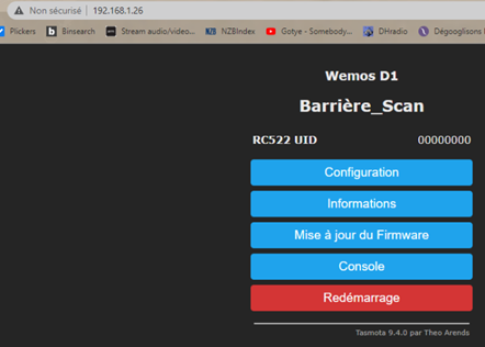
Go to the home page of your Wemos by entering the IP address found previously then click on « configuration »
Then on « Other configuration » and paste the following text in the « Template » box:
{"NAME":"Wemos D1","GPIO":[1,1,1,1,1,1,1,1,1,1,1,1,1,1],"FLAG":0,"BASE":18}
Check the « Enable » box and take the opportunity to give a nice name to your Wemos:
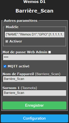
Click then on « save », the Wemos restarts.
After this, click on « configuration » then on « module configuration ».
In the « Module type » field, choose « Wemos D1 », click on « save », the module restarts (again!)
3.3 The MQTT
In the « configuration » page, go to « MQTT configuration » and enter the characteristics of your Gladys instance
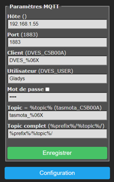
Click on « save », the module restarts (yes, again!)
3.4 The GPIOs
We will now explain to Tasmota that we are connecting an RFID card reader. To do this, go to the « Configuration » page, « Module Configuration » and select the following settings:
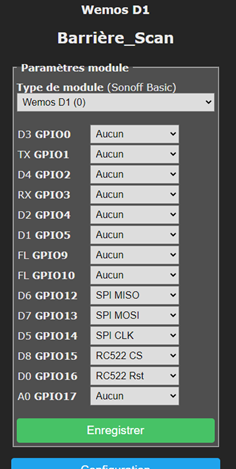
Save, the module restarts (and it’s not a joke!)
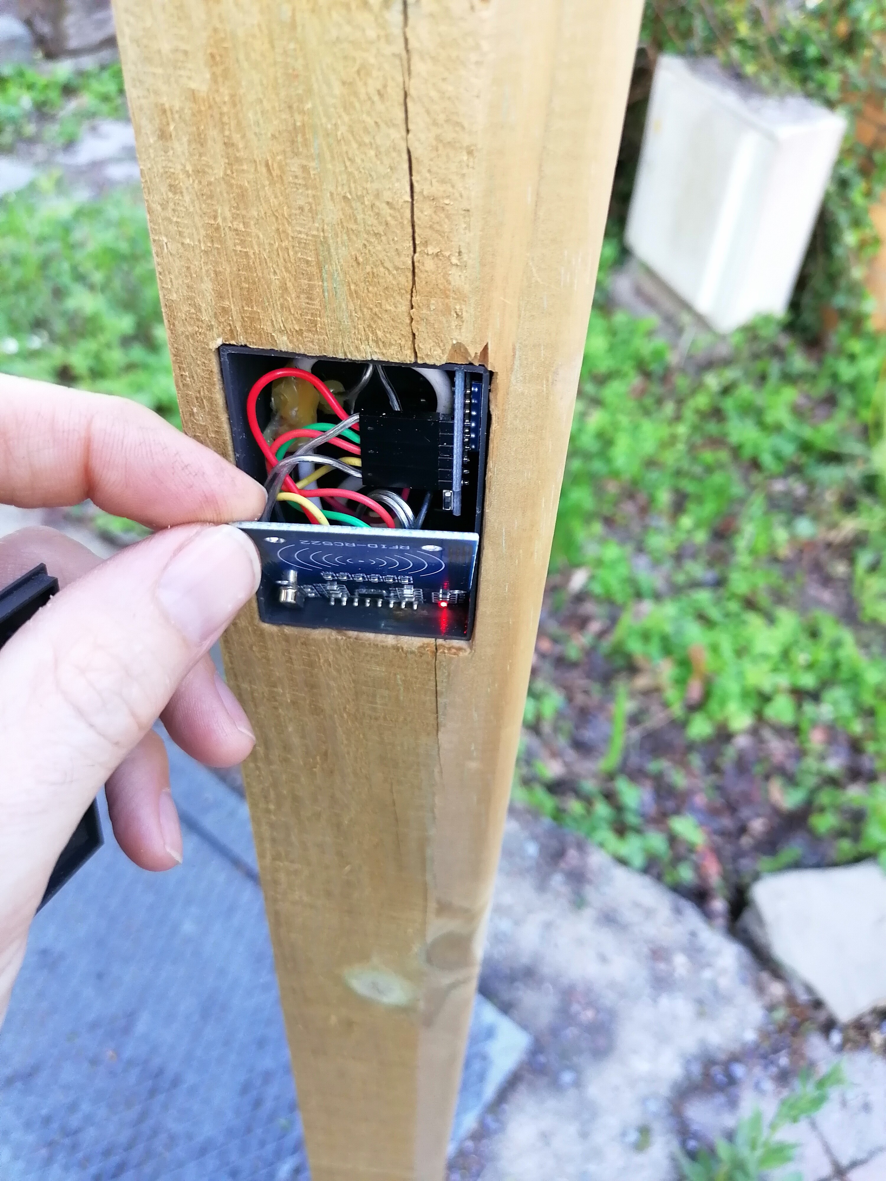
4. The module configuration is complete, time for the connections (so, unplug the power source!).
4.1 Here’s how to connect everything (by soldering, recommended, or with DuPont cables, easier):
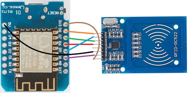
And the same, in a table:
| Wemos D1 Mini | RC522 |
|---|---|
| D8 | SDA |
| D7 | MOSI |
| D6 | MISO |
| D5 | SCK |
| D0 | RST |
| G | GND |
| 3V3 | 3.3V |
4.2 Let’s check that it works!
Plug the microUSB cable into the Wemos. A red indicator LED should light up on the RC522.
Go to the module configuration page (you know, the IP address…) and click on « console ». In the list of displayed information, the following should appear:
00:00:00.059 SPI: Hardware using GPIO14(CLK), GPIO13(MOSI) and GPIO12(MISO)
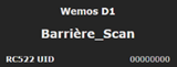
00:00:00.062 Project tasmota Barrière_Scan Version 9.4.0(TasmoCompiler-esp82664M)-2_7_4_9(2021-05-03T14:19:55)
00:00:00.118 MFR: RC522 Rfid Reader detected v2.0
Bravi! (a bravo, bravi, it’s well known!)
To test this, scan one of your RFID cards provided or collected and take the opportunity to copy the codes (usually 8 to 16 hexadecimal values). The scanned values are displayed on the home page or in the console:
5. Configuration in Gladys
5.1 Via the Tasmota integration (in a more or less near future)
5.2 Via the creation of a fake device (a « fake device ») in MQTT
5.2.1 Go to the « integrations » tab and choose MQTT. Then click on « New »:
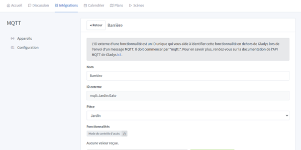
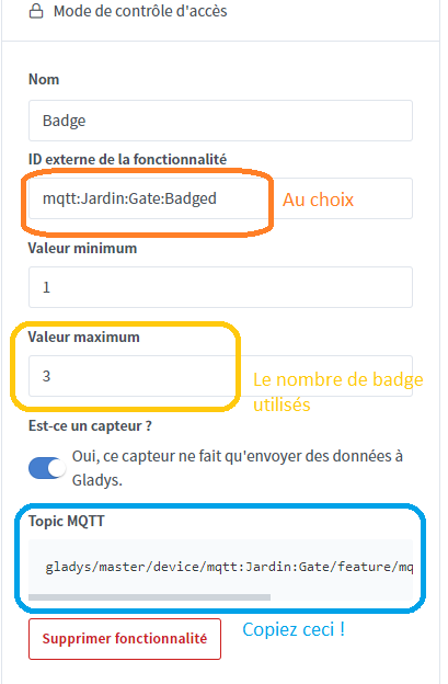
In « features », choose « Access control mode » and complete as follows (or as you see fit after all!). Then, COPY the text (in full) noted in « MQTT Topic »:
Save! (No restart this time!)
5.2.2 Return to the Tasmota configuration interface (the IP address from the beginning)
Now you need to tell your module what to do when you scan an RFID chip. And it’s very simple… You want it to tell Gladys! To do this, we will use the « rules ». It works like this:
In short, when we receive the value of the RFID badge (0F0F0F0F in the example), we publish on the dedicated topic of Gladys copied just before (gladys/master/device/mqtt:Jardin:Gate/feature/mqtt:Jardin:Gate:Badged/state in the example) the desired number (3 in the example)
Rule1 ON RC522#UID=0F0F0F0F DO publish gladys/master/device/mqtt:Jardin:Gate/feature/mqtt:Jardin:Gate:Badged/state 3 ENDON
To add others, take the previous command by adding a « + » at the beginning such as:
Rule1 +ON RC522#UID=1F1F1F1F DO publish gladys/master/device/mqtt:Jardin:Gate/feature/mqtt:Jardin:Gate:Badged/state 2 ENDON
This rule will then be added to the previous one.
Last thing! You need to activate the rule. Just type the command:
Rule1 1
And now?
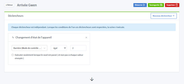
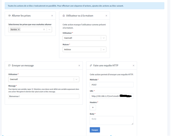
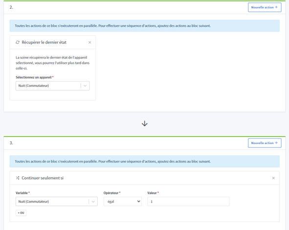
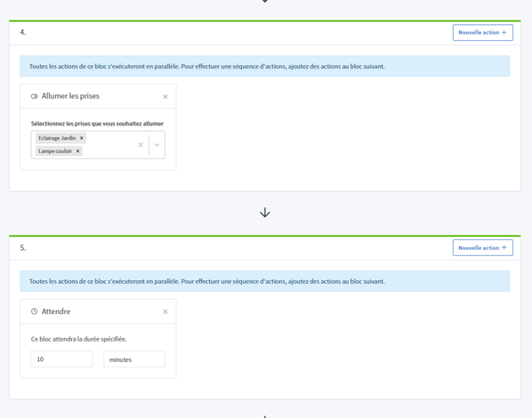
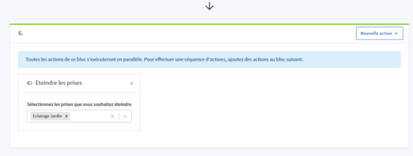
6. Use in Gladys scenes
7. A bonus?
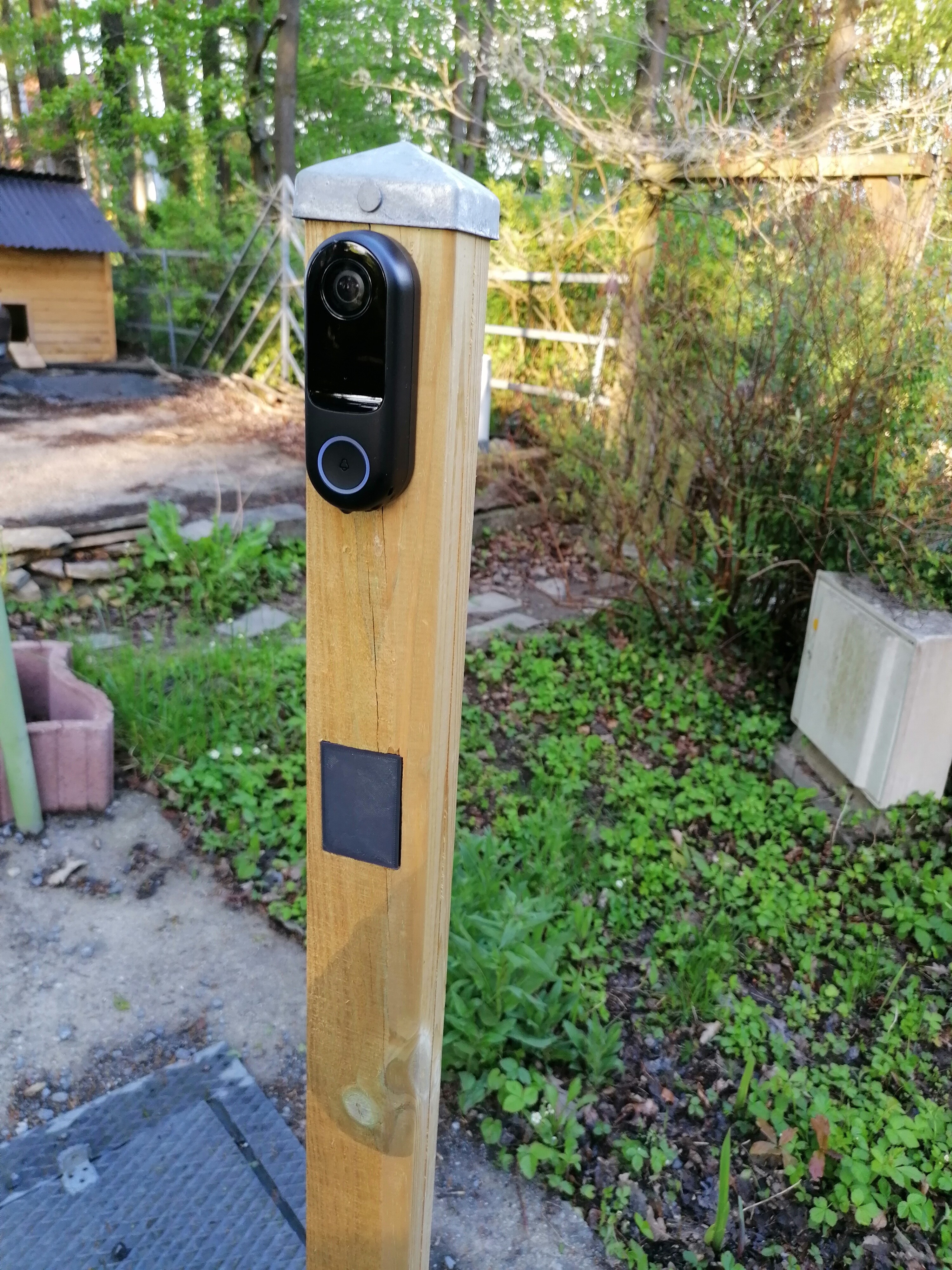
I drew a box to put this inside… If you have something to print, here are the files!
The lid
The case