[TUTORIEL] Connaitre la capacité restante de sa cuve eau de pluie

Have you correctly modified the information below in the program so that it matches your situation?

[quote=« jerome, post:1, topic:6272 »]

/* WIFI */

#define wifi_ssid "*********" // your wifi ssid
#define wifi_password "**************" // your wifi password

/*

Yes. Here are my details:


#include <ESP8266WiFi.h>
#include <PubSubClient.h>

/* WIFI */

#define wifi_ssid « xxx-Hxxx-9xxxxx » // your wifi ssid
#define wifi_password « abcdefghi » // your wifi password

/* MQTT */

#define mqtt_server « 192.168.1.xxx » // IP of the Pi where Gladys is installed
#define mqtt_user « gladys » // username
#define mqtt_password « abcdefgeijklm » // MQTT password
#define gladys_topic « gladys/master/device/mqtt:citerne1:capteur-ultrason/feature/mqtt:citerne1:capteur-ultrason:quantite/state »
#define mqtt_cuve « mqtt:citerne1:capteur-ultrason » // Tank sensor topic

I think that should be correct
:wink:

Alright, you need to check that your programmed module is working.
That’s what @jerome was asking you.
You connect your module to the PC, open the Arduino IDE and open the ‹ Serial Monitor › window from the ‹ Tools › tab
That should allow you to follow the program’s progress through its different stages.

When I open the serial monitor I get this :

09:50:25.305 -\u003e
09:50:25.305 -\u003e ets Jan 8 2013,rst cause:4, boot mode:(3,6)
09:50:25.305 -\u003e
09:50:25.305 -\u003e wdt reset
09:50:25.305 -\u003e load 0x4010f000, len 3460, room 16
09:50:25.305 -\u003e tail 4
09:50:25.305 -\u003e chksum 0xcc
09:50:25.305 -\u003e load 0x3fff20

The flash didn’t go well, are you sure the selected board was the right one?

[

I think so

And by choosing ‹ D1 mini (clone) › and/or ‹ upload speed 115200 › and then reflash?
If that still doesn’t work, you’ll have to call on a friend :slight_smile:

When you say « reflash » do you mean « Upload »?

I have the same result as with “LOLIN

1 Like

Which website did you buy your card from? Can you give us the link so we can find which one it corresponds to?

On amazon.fr
https://www.amazon.fr/dp/B09MT1GKS7?psc=1&ref=ppx_pop_dt_b_product_details

Product Description
Features:
Product parameters:
This board contains 11 digital input/output pins; all pins support interrupts, PWM, I2C, 1-Wire (except D0) and a micro USB connector; 1 input (below 3.2V) compatible with Arduino; 500mA resettable fuse
Module:
Adopting a small convenient size, this ESP-12F (ESP8266)-based development board can help your project save space

Specifications:
Color: black
Size: 34 x 25 x 7 mm / 1.33 x 0.98 x 0.28 inches

How to use:
How to get started:
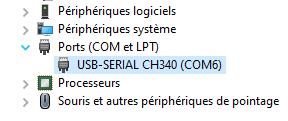
Set up the driver: before using the development board, you must install the CH340g driver.
Hardware package installation:
There are 2 ways to install the hardware package: Boards Manager or GIT.

Package includes:
2 * Development boards

Notes:
Due to manual measurement, please allow slight size differences.

  • Module: with a small and convenient size, this ESP-12F (ESP8266)-based development board can help your project save space
  • WIFI development board: built-in 5V 1A switching regulator, 4 MB
  • Product parameters: this board contains 11 digital input/output pins; all pins support interrupts, PWM, I2C, 1-Wire (except D0) and a micro USB connector; 1 input (below 3.2V) compatible with Arduino; 500mA resettable fuse
  • Product features: this Internet development board is well suited to Arduino and can be programmed in the Arduino IDE and supports OTA (over-the-air) updates
  • Package includes: you get 2 development boards, each module contains 6 pin headers

See more details

Did you successfully download the CH340G driver? Did the operation go smoothly?

In Windows 10’s Device Manager I can see CH340

Would you please, only for testing purposes, install Tasmota on it?
If yes, it’s very simple. Go to Install Tasmota
Connect your Wemos, choose the Tasmota FR version, ESP8266 module and Flash!
If everything worked, your module should now be broadcasting a WiFi access point name like Tasmota-xxxxxx
We’ll see whether it flashed or not…

It seems to have worked:

Sonoff Basic

Tasmota

Program Version 12.2.0(tasmota)
Build Date & Time 2022-10-17T08:43:36
Core/SDK Version 2_7_4_9/2.2.2-dev(38a443e)
Uptime 0T00:00:41
Flash write counter 9 at 0xFB000
Boot Count 3
Restart Reason Software/System restart
Friendly Name 1 Tasmota
AP1 SSID (RSSI) Prxxxx-Hxxxe-xxxxxxx (40%, -80 dBm) 11n
Host Name tasmota-43xxxx-7xxx
MAC Address xx:xx:xx:xx:xx:xx
IP Address (wifi) 192.168.1.xx
Gateway 192.168.1.1
Subnet Mask 255.255.255.0
DNS Server 1 192.168.1.1
DNS Server 2 0.0.0.0
HTTP API Enabled
MQTT Host
MQTT Port 1883
MQTT User DVES_USER
MQTT Client DVES_435BF3
MQTT Topic tasmota_%06X
MQTT Topic Group 1 cmnd/tasmotas/
Full MQTT Topic cmnd/tasmota_435BF3/
Backup MQTT Topic cmnd/DVES_435BF3_fb/
MQTT No Retain Disabled
Emulation None
ESP Chip Id 4414451 (ESP8266EX)
Flash Chip Id 0x16405E (DOUT)
Flash Size 4096 KB
Program Flash Size 1024 KB
Program Size 628 KB
Free Program Space 372 KB
Free Memory 26.1 KB

So, it’s not a problem with drivers or hardware. We’re making little progress but we’re moving forward.
If you want to play with Tasmota, distance sensor support is native (in cm, not in %). That could validate the sensor’s operation/wiring.
The problem therefore comes either from the Arduino IDE configuration or from the program itself.
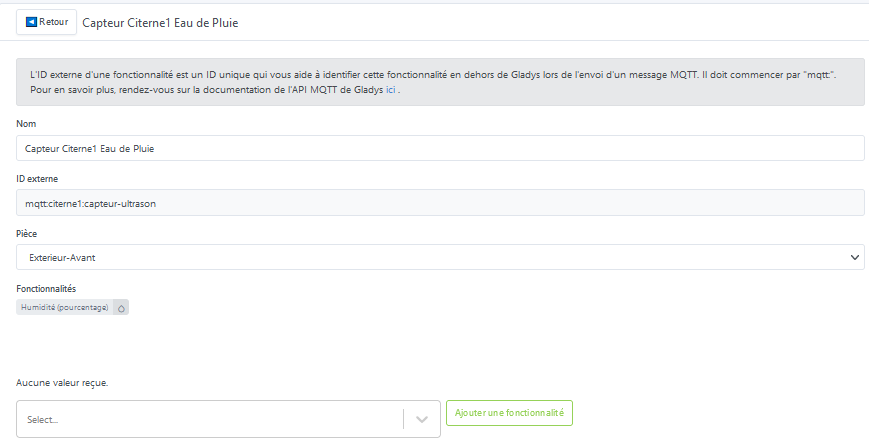
Which pins did you connect your sensor to?

Connected as suggested in the first message

Tasmota still active this morning

That’s another thing. I don’t know anything about Tasmota
:wink:

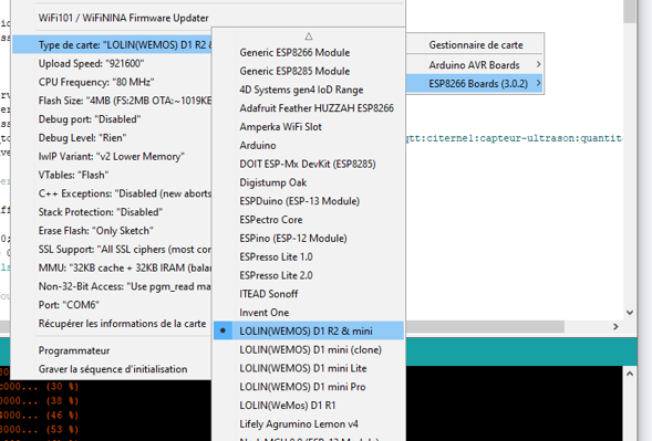
I think the problem comes from the Arduino IDE and the selected board type, because the program appears to have been uploaded but doesn’t start, judging by the output in the serial monitor console.

Normally you should see a message like … connecting to 192.168.XX.XX then connecting to MQTT

Okay, I reinstalled everything
I flashed the ESP8266
Installed Arduino IDE 2.0.1
But in the library I can’t find ESP8266Wifi
There is « ESP-WiFi settings » or « ESP_WiFiManager »
Any idea?